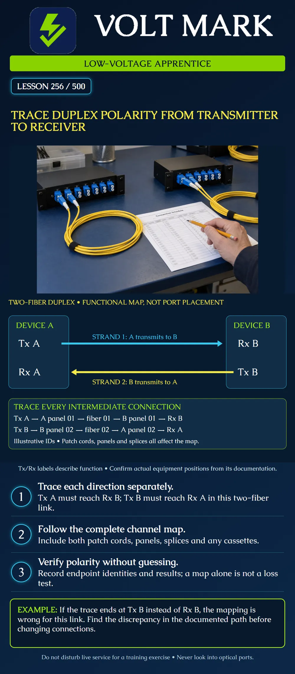
Trace both directions of a conventional two-fiber duplex link through all intermediate connections. Identify whether each transmitter reaches the intended receiver.
For the system illustrated, one strand carries the signal from transmitter A to receiver B. The other carries the signal from transmitter B to receiver A. Fluke Networks and ICC describe this transmitter-to-receiver relationship for duplex fiber applications.
The poster arranges the functional labels to make the paths readable. It does not prescribe left/right or top/bottom port positions on a transceiver. Consult the actual equipment markings and documentation, including the viewing orientation.
This lesson's diagram is specifically a two-fiber arrangement. Do not apply the drawing unchanged to a single-fiber bidirectional system or to a multifiber parallel-optics interface.
The cyan arrow runs from Tx A to Rx B on Strand 1. The yellow arrow runs from Tx B to Rx A on Strand 2. Both arrows terminate at receivers. The numbered strand names identify the illustrative paths, not universal color assignments.
Below the arrows, the example traces the same functions through fictional panel labels: Tx A → A panel 01 → fiber 01 → B panel 01 → Rx B. Tx B → B panel 02 → fiber 02 → A panel 02 → Rx A.
A panel position does not become a transmitter or receiver on its own. Its role depends on the equipment and patching connected to it.
Prepare a worksheet with columns for starting function, near-end patch cord, near-end panel position, intermediate fiber/splice mapping, far-end panel position, far-end patch cord and destination function.
Follow one path all the way before tracing the other. Do not skip a cassette or splice because its labels look similar. A numbered fiber can be reassigned at an intermediate connection, and that change must appear in the record.
Manufacturer polarity methods provide organized ways to maintain the intended map. Their connector orientation and component requirements must be followed as a system. This lesson does not select a universal crossover location or require a fixed number of physical cord flips.
The instructor provides these four records for a disconnected training system: A equipment Tx is patched to A panel 01. A panel 01 maps through the cable plant to B panel 01. B panel 01 is patched to B equipment Tx. A equipment Rx is patched through the other recorded path to B equipment Rx.
Write the two resulting endpoints: Tx A reaches Tx B. Rx A reaches Rx B.
The records do not meet this link's required functional map. That conclusion is based on tracing the records, not on observing an actual link failure.
Next compare those records with an approved design that calls for B panel 01 to reach Rx B and B panel 02 to reach Tx B. The discrepancy is in the far-end equipment patching relative to this design. That is a specific finding. “All the fiber is bad” is not supported.
The classroom answer is to document the discrepancy and identify the reviewed correction. It is not an instruction to swap a live pair without authorization, interface checks and the applicable service procedure.
A second drawing uses the following IDs: Tx A → PA-07 → cable C3/fiber 19 → PB-22 → Rx B. Tx B → PB-23 → cable C3/fiber 20 → PA-08 → Rx A.
The panel numbers differ across the link, but the functional map is correct as documented. Equal numbers are not a requirement for polarity. Trace the actual relationship rather than assuming 07 must arrive at 07.
There are two directed signal paths in this example. Counting two continuous fibers does not by itself prove that their endpoints are assigned correctly.
A correct endpoint map is one requirement. It does not establish loss, cleanliness, connector condition, supported wavelengths, application reach or transceiver compatibility. Likewise, a power reading at one point does not document the complete two-direction map.
Use the approved test procedure, suitable instruments and the specified acceptance criteria to verify the installed system. Record what was actually tested and retain endpoint identities. A link indication is useful operational evidence but is not a replacement for the required installation records.
Use drawings and disconnected instructor-prepared samples:
Do not look into fiber ends or ports. Do not disconnect an operating campus, security, industrial or life-safety link for this exercise.
Trace the supplied second drawing one path at a time. Start at Tx A, follow PA-07 to cable C3/fiber19, then PB-22 to Rx B. The recorded destination is the required opposite receiver. Start the return path at Tx B, follow PB-23 to C3/fiber20, then PA-08 to Rx A. The second recorded destination also meets the required function.
Record both complete chains rather than merely writing two fibers present. PA-07 and PB-22 need not share a number because the documented map connects them. This paper evidence supports the functional map only; it provides no measured insertion loss or permission to change a working patch arrangement.
Mistake: Signing off polarity after confirming that two fibers are continuous. Correction: Trace both directions explicitly: Tx A must reach Rx B, and Tx B must reach Rx A in this two-fiber design.
Mistake: Declaring the PA-07 to PB-22 route wrong because panel numbers differ. Correction: Follow the documented intermediate mapping and destination function; equal panel numbers are not a polarity requirement.
Mistake: Flipping every accessible duplex cord after finding Tx-to-Tx in the records. Correction: Locate the discrepancy against the approved complete map and refer that specific correction for authorization; several blind flips can conceal or recreate the fault.
Fluke Networks, Fiber Polarity Basics for Duplex Applications: https://www.flukenetworks.com/blog/cabling-chronicles/b-c-s-fiber-polarity ICC, What are the polarities of duplex fiber jumpers? https://icc.com/help/polarities-duplex-fiber-jumpers/
Texas journeyman, 15 questions, scored by topic against the 70% mark. No card, and no account needed to start.
Free study material for low-voltage apprentices. This is a national foundation course: requirements differ by state and by local jurisdiction, and a practice that is common in one place is not a rule everywhere. Nothing here is a licence, a certification, or authority to work unsupervised, and completing it does not count as apprenticeship hours or continuing-education credit. Check the codes adopted where you are working, the licensing authority for that work, and your employer's safety programme. VoltMark is not affiliated with, endorsed by, or sponsored by NFPA, OSHA, NICET, BICSI, FOA, or any state or local licensing authority.

Electrician licensing exam prep: practice questions, timed exam simulations, and step-by-step help finding every answer in the NEC.