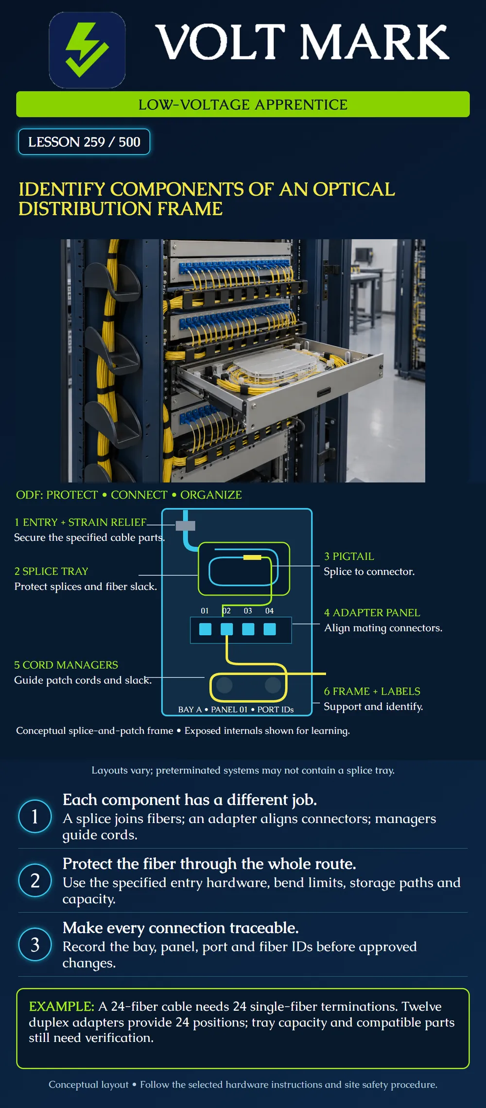
Given an approved drawing or an isolated training assembly, identify the hardware that supports, protects, terminates and organizes optical fibers. Explain how a cable fiber reaches a labeled connector position without confusing the splice, pigtail, adapter or patch cord.
An optical distribution frame (ODF) is an organized location for fiber connections. Its mechanical structure supports the installed housings and cable-management components. The selected system can include splice storage and patching, or use preterminated assemblies. The poster is a conceptual splice-and-patch example, not the internal routing instructions for a particular manufacturer's product. It exposes normally protected parts so their relationships are visible. Colors show component relationships, not a fiber identification code.
Read the drawing from incoming cable to protected fiber, splice, pigtail connector, adapter, patch-cord connector and destination. This is a connectivity trace, not a direction of signal flow. A circuit can transmit in either direction according to its design. A frame may also contain preterminated cassettes or other specified passive components, so do not invent a splice where the approved drawing shows none.
A work package calls for 24 individually terminated fibers. Assume each selected duplex adapter provides two single-fiber connection positions. Then 12 duplex adapters × 2 positions = 24 positions. This arithmetic only checks that part of the count. Separately verify the correct adapter panels, compatible pigtails, connector polish, splice holders, tray capacity and routing space. If an approved tray holds 12 of the specified single-fiber splices, 24 ÷ 12 = 2 trays are needed for the exercise. That 12-splice capacity is an exercise assumption, not a rule for all trays. A count of 24 terminations does not mean 24 conventional two-fiber duplex circuits; paired that way, it supports 12 pairs before reservations or other design constraints.
Using a training drawing, label the six components. Make one fictional record: Building A / Bay A / Panel 01 / Position 02 / Cable C-07 / Fiber 02. Add the documented patch-cord destination and circuit ID from the exercise work order. If the destination is missing, mark it unresolved rather than guessing. Identify where the approved hardware manual specifies cable restraint, tray routing and cord storage. Do not open trays, unplug service cords or inspect live ends merely to complete this exercise.
For the supplied 24-fiber splice-and-patch training design, calculate positions first: 24 individual terminations divided by two positions per selected duplex adapter gives twelve adapters. At the assumed twelve compatible single-fiber splices per tray, 24 divided by 12 gives two trays. Record twenty-four pigtails, subject to the selected assembly's actual contents, plus the required panels and management hardware. These counts are for one described termination location.
Trace one position from cable fiber to protected splice, pigtail, rear adapter connection, front patch cord and its documented destination. The adapter does not replace the splice. The counts and trace establish a paper component relationship; actual hardware compatibility, capacities, restraint and routing remain separate checks.
Mistake: Drawing the adapter as the joint between a bare cable fiber and the pigtail. Correction: Place that joint in the specified splice arrangement; the adapter aligns the pigtail connector with a compatible patch-cord connector.
Mistake: Ordering twelve duplex adapters and recording twenty-four two-fiber circuits. Correction: Count twenty-four individual positions; conventional two-fiber pairing yields twelve pairs before reservations, with the remaining hardware checked separately.
Mistake: Treating an entry protector as the cable's strain relief. Correction: Identify the separate approved load-restraint hardware and attachment instructions; a protected opening alone does not secure cable loads.
Corning, Frame and Cable Management product drawings: https://www.corning.com/optical-communications/worldwide/en/home/Resources/product-drawings/frame-and-cable-management.html The public product table documents frames, jumper-management panels, cylindrical hubs, inter-bay storage and product-specific strain-relief brackets. Those examples support the distinction between support, restraint and cord-management hardware.
CommScope, Optical Distribution Frames: https://www.commscope.com/network-type/central-officeheadend/optical-distribution-frames-odf/ Public overview for the ODF context; this lesson does not claim detailed installation requirements from it.
Fiber Optic Association, Outside Plant Splicing and Termination: https://thefoa.org/tech/ref/OSP/term.html Reference for pigtail termination and protected splice-tray storage. No tray-size rule is adopted.
This is a training overview, not authorization to disturb circuits or a complete installation procedure.
Texas journeyman, 15 questions, scored by topic against the 70% mark. No card, and no account needed to start.
Free study material for low-voltage apprentices. This is a national foundation course: requirements differ by state and by local jurisdiction, and a practice that is common in one place is not a rule everywhere. Nothing here is a licence, a certification, or authority to work unsupervised, and completing it does not count as apprenticeship hours or continuing-education credit. Check the codes adopted where you are working, the licensing authority for that work, and your employer's safety programme. VoltMark is not affiliated with, endorsed by, or sponsored by NFPA, OSHA, NICET, BICSI, FOA, or any state or local licensing authority.

Electrician licensing exam prep: practice questions, timed exam simulations, and step-by-step help finding every answer in the NEC.