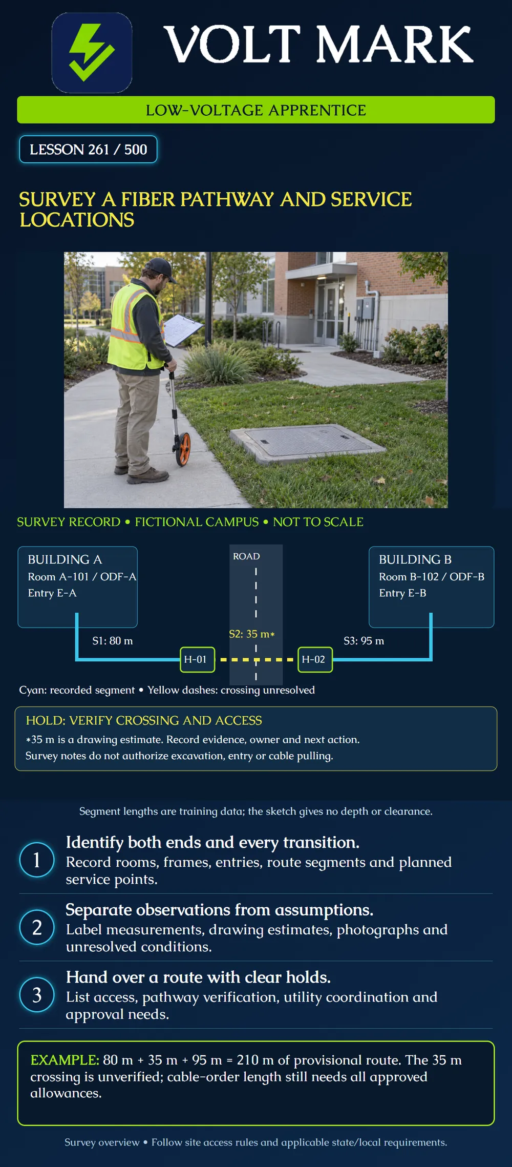
Produce a route survey record that identifies fiber endpoints, pathway segments, transitions and service locations. Clearly distinguish verified observations, estimates and unresolved conditions before the installer plans cable placement.
Obtain the current approved site drawing, work scope and permission to access the survey area. Record the drawing revision, survey date, responsible personnel and link identifier. Confirm which buildings, rooms and equipment locations the work actually connects. A line between buildings on a campus map is not a complete fiber pathway.
Identify both service endpoints using building, floor, room, frame or cabinet, panel and intended termination details where known. Confirm labels against the authorized documentation. Record access contacts and service restrictions. Do not disconnect circuits or enter restricted areas to settle an unknown label; make it an explicit follow-up item.
Break the route into segments between identifiable points. These may include room exits, building entries, pull locations, handholes, transition enclosures and termination spaces. For each segment, record the proposed or existing pathway type and how its condition was established. A drawing, a visible surface feature and a completed pathway-verification record are different forms of evidence.
Note changes in elevation, direction and environment, plus crossings and locations where later installation access may be difficult. Record the proposed cable delivery and staging area separately from the final cable route. The survey supplies facts for the pulling plan; it does not choose pulling forces, bend limits or an installation method by guesswork.
Identify the locations intended for termination, splicing, pulling access and permitted slack storage. These functions may occur in different places. Record identifiers, access arrangements, available working space as observed, and relevant environmental concerns. Do not assume that every handhole is a splice location or that spare space automatically permits a cable loop.
For each building entry, record the intended pathway transition and the design information still needed. The approved design must address the applicable cable environment, protection and penetration treatment. This lesson does not assign a universal building-entry cable length, burial depth, utility separation or firestop system.
Use clear evidence labels such as OBSERVED, MEASURED, DRAWING ESTIMATE and NOT VERIFIED. Record the measurement method and units. A satellite-map distance may omit vertical runs, building interiors, offsets and service allowances. A surface route trace does not establish underground depth or prove that a duct is clear.
Give every unresolved item an owner and required next action. Useful entries include “access confirmation needed from facilities,” “crossing method awaiting designer review,” or “pathway condition not verified.” Keep the unresolved item visible on both the sketch and the written record.
The sketch connects ODF-A in Room A-101 to ODF-B in Room B-102. H-01 and H-02 are identified access locations. S1 is recorded as 80 m, S2 is a 35 m drawing estimate across a road, and S3 is recorded as 95 m. These numbers describe the whole illustrated segments for the exercise, not a surveyed real campus.
80 + 35 + 95 = 210 m of provisional route. S2 remains unresolved, so the sum is not a verified installed length or permission to cross the road. Suppose a revised authorized survey later changes S2 to 42 m: 80 + 42 + 95 = 217 m. The route total increases by 7 m. Cable-order length still needs the designer's approved treatment of termination lengths, service slack and any other omitted portions. Do not add a memorized universal percentage.
A survey does not authorize excavation or entry into underground structures. Follow the employer's site access and hazard-control procedures. Where excavation is planned, OSHA's construction excavation rule addresses determining underground utility locations and contacting utility owners before excavation; approaching existing installations requires safe location methods. State and local notification, permitting and other applicable requirements must also be resolved. This lesson provides no universal waiting period or clearance-to-dig declaration.
Do not open an enclosure, enter a space or work in a traffic exposure merely because it appears on the route drawing. Record the need for an authorized investigation instead. Do not assume public utility notifications cover every privately owned campus facility.
Link ID / drawing revision: From location / to location: Segment ID / pathway description: Length / units / method / evidence status: Photo or document reference: Transitions / service locations: Access and service restrictions: Unresolved condition / responsible person / next action: Reviewed by / date:
Use the form for S2. A suitable answer identifies H-01 to H-02, records 35 m as a drawing estimate, notes the road crossing as unresolved, and requests the authorized route/access/utility verification needed for design review. It does not declare the crossing ready to install.
Mistake: Marking S2's duct condition verified from the road-crossing line on the drawing. Correction: Retain DRAWING ESTIMATE or NOT VERIFIED as applicable and assign the authorized pathway investigation to an owner.
Mistake: Ordering 210 m of cable from the provisional route total. Correction: Resolve the 35 m estimated segment and separately document approved termination and service allowances; the route sum is not an installed cable-order length.
Mistake: Treating a listed handhole as both a splice point and permission to enter. Correction: Confirm its planned function and obtain the separate access and hazard-control authorization; a survey label establishes neither.
Fiber Optic Association, Fiber Optic Network Design: https://www.thefoa.org/tech/ref/basic/design.html Reference for visiting the route, evaluating project conditions and planning service/splice slack storage; no detailed installation dimensions are adopted here.
Fiber Optic Association, Planning a Fiber Optic Installation: https://www.thefoa.org/tech/ref/install/plan.html Reference for coordinating a documented design, permits, installation scheduling, staging and safety preparation.
OSHA, 29 CFR 1926.651, especially (b)(1)–(3): https://www.osha.gov/laws-regs/regulations/standardnumber/1926/1926.651 Reference for the distinction between route observations and required underground-utility coordination before excavation. No state-specific approval or nationwide waiting period is claimed.
Texas journeyman, 15 questions, scored by topic against the 70% mark. No card, and no account needed to start.
Free study material for low-voltage apprentices. This is a national foundation course: requirements differ by state and by local jurisdiction, and a practice that is common in one place is not a rule everywhere. Nothing here is a licence, a certification, or authority to work unsupervised, and completing it does not count as apprenticeship hours or continuing-education credit. Check the codes adopted where you are working, the licensing authority for that work, and your employer's safety programme. VoltMark is not affiliated with, endorsed by, or sponsored by NFPA, OSHA, NICET, BICSI, FOA, or any state or local licensing authority.

Electrician licensing exam prep: practice questions, timed exam simulations, and step-by-step help finding every answer in the NEC.