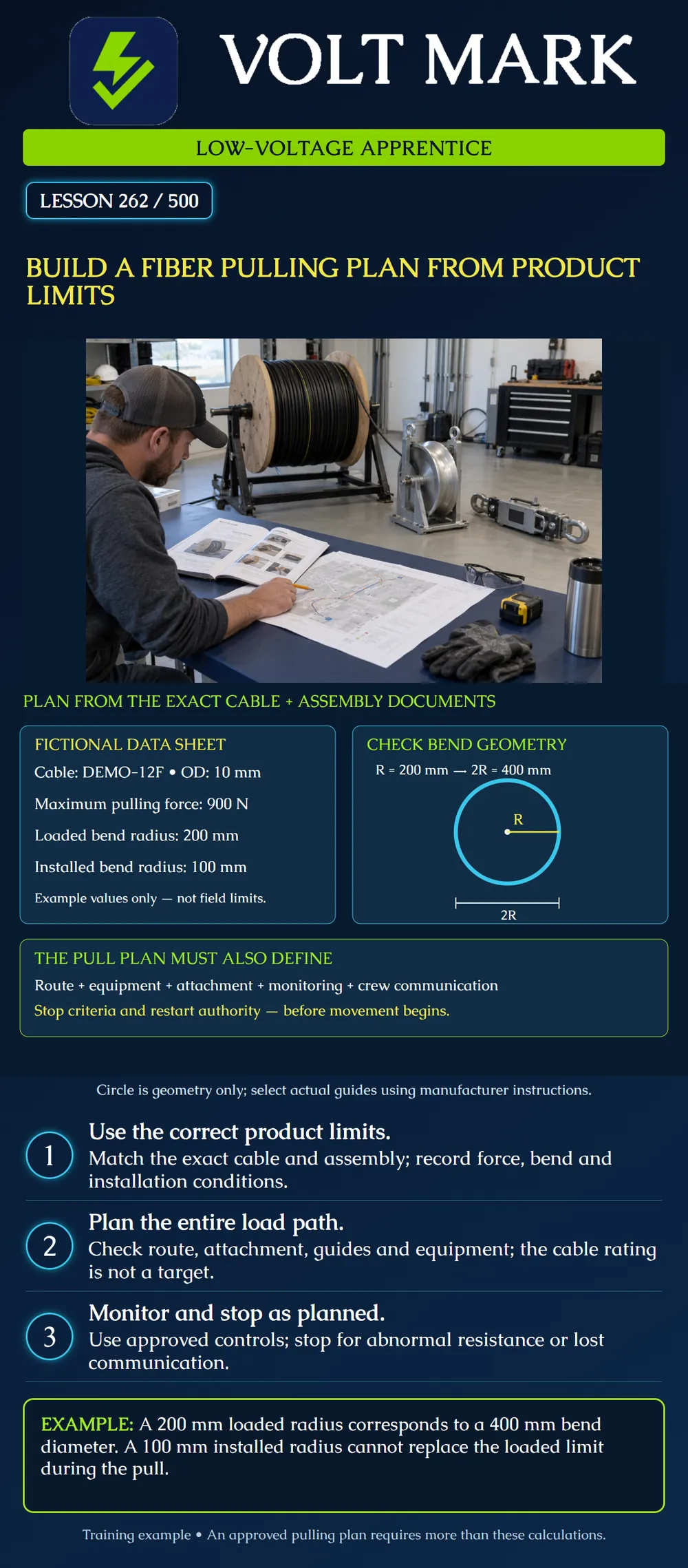
Turn the selected cable and assembly documents into a traceable pulling-plan checklist. Distinguish maximum pulling force, loaded bend radius and installed bend radius. Identify the controls and unresolved questions that must be addressed before installation.
Record manufacturer, full part number, reel or assembly identification, data-sheet revision and the applicable installation procedure. Check that the documents match the supplied construction and installation method. A bare fiber's bend specification is not a jacketed cable's installation limit. A preterminated assembly can also have pulling-head, breakout or connector-protection requirements that do not appear in a generic cable table.
Extract the maximum permitted pulling force and its units, minimum bend radius under installation load, minimum installed bend radius, permitted installation conditions and the manufacturer's attachment instructions. Record where each value came from. Keep the operating-temperature range separate from the allowed installation-temperature range when the manufacturer distinguishes them. Missing or conflicting values are a HOLD item for the responsible reviewer or manufacturer.
Maximum pulling force is a ceiling, not the desired pulling force. The installed bend radius describes the applicable after-installation condition; it cannot automatically be used while the cable is being pulled under load. A minimum bend radius means the bend must be no tighter than that radius. Increasing the bend radius produces a gentler curve.
The approved arrangement must satisfy the cable, assembly and relevant equipment requirements together. Do not select equipment solely because its nominal force capacity exceeds the cable rating. The attachment method, guide geometry, supporting equipment, load measurement and operating controls also matter. A reel flange diameter is not automatically the guide's usable cable-bending diameter.
Start with the verified pathway survey. Identify reel position, pulling direction, bends, entrances, intermediate access, vertical changes and the destination. The responsible planner evaluates the expected loads for that route and the applicable placement method. Total route length alone does not determine pulling force. A longer route or more severe bends may require a different plan, intermediate assistance or divided operations; do not improvise those changes in the field.
List the approved pulling attachment, compatible pulling line, any specified swivel, guides, rollers and monitoring or limiting equipment. Identify how the cable will be protected from crushing, twisting and sharp edges. The next lesson addresses equipment preparation in more detail. This lesson does not provide a grip-installation procedure or a universal equipment list.
The plan should name who directs the operation, who controls feed and pulling equipment, where observers are needed, how they communicate and who can order a stop. Define stop criteria for abnormal resistance, equipment trouble, a lost communication link or an observed damaging condition. Define who evaluates the problem and authorizes restart after correction.
The selected monitoring arrangement must relate its readings to the cable load being controlled. Do not assume a display at an arbitrary point measures every local load. The responsible planner must account for the arrangement, measurement uncertainty and control response. Do not invent a universal percentage below the cable maximum as a shutdown setting.
The poster uses a made-up DEMO-12F cable: outside diameter 10 mm, maximum pulling force 900 N, loaded minimum bend radius 200 mm and installed minimum bend radius 100 mm. These are teaching assumptions, not published ratings for a real cable.
A circle with radius 200 mm has diameter 2 × 200 = 400 mm. The installed radius corresponds to 2 × 100 = 200 mm diameter. The smaller installed value does not satisfy the example's loaded requirement. If a proposed cable path bends at a radius of 150 mm during pulling, it is 50 mm below the required 200 mm radius and must be revised.
The diagram illustrates radius and diameter only. It does not specify a sheave's flange size, groove design or an approved pulling arrangement. Confirm how the manufacturer defines the relevant cable path and equipment dimensions. Also verify whether the pulling head or other assembly elements impose a larger minimum bend.
Suppose the planning review proposes a configuration with a documented 800 N allowable working force for one relevant component while the example cable permits 900 N. The cable's 900 N rating cannot justify exceeding that component's 800 N allowance. If the planned force is 850 N, the arrangement fails that check by 50 N. Redesign or resolve it before work. Passing this simple comparison would still not prove the complete installation safe or acceptable.
Cable / assembly identification: Documents / revisions: Maximum pulling force / units / source: Loaded minimum bend radius / source: Installed minimum bend radius / source: Other installation conditions: Route / pull direction / feed and pull locations: Approved attachment / guides / equipment: Predicted loads and review reference: Monitoring / controls / stop criteria: Crew communication / stop and restart responsibilities: Unresolved items / reviewer / approval date:
Mistake: Setting the pull target to the cable's 900 N maximum. Correction: Treat the rating as a ceiling and obtain the reviewed operating controls for the complete route and assembly.
Mistake: Using the 100 mm installed radius at a guide during the loaded pull. Correction: Compare the actual cable path with the fictional 200 mm loaded minimum and any stricter assembly requirement.
Mistake: Approving 850 N because the cable allows 900 N despite an 800 N component limit. Correction: Hold that arrangement: the planned force exceeds the component allowance by 50 N, so the responsible planner must resolve it before work.
Corning SRP 005-026, Issue 11, October 2018: https://www.corning.com/catalog/coc/documents/standard-recommended-procedures/005-026.pdf Read the handling-limit and monitoring sections. This is a procedure for self-supporting figure-8 aerial cable, used here only to establish the need for product-specific limits, loaded versus installed bend conditions and coordinated monitoring. Its aerial speeds, loads and generic formulas are not adopted for other cable types. Current instructions for the actual selected product govern.
Fiber Optic Association, Installing Fiber Optic Cable: https://www.thefoa.org/tech/ref/install/installcbl.html Accessed as a general installation reference. This lesson's numerical examples are original fictional exercises, not product ratings.
Texas journeyman, 15 questions, scored by topic against the 70% mark. No card, and no account needed to start.
Free study material for low-voltage apprentices. This is a national foundation course: requirements differ by state and by local jurisdiction, and a practice that is common in one place is not a rule everywhere. Nothing here is a licence, a certification, or authority to work unsupervised, and completing it does not count as apprenticeship hours or continuing-education credit. Check the codes adopted where you are working, the licensing authority for that work, and your employer's safety programme. VoltMark is not affiliated with, endorsed by, or sponsored by NFPA, OSHA, NICET, BICSI, FOA, or any state or local licensing authority.

Electrician licensing exam prep: practice questions, timed exam simulations, and step-by-step help finding every answer in the NEC.