Prepare for supervised jacket access by confirming cable identity and isolation, selecting the applicable tools and documents, and recognizing conditions that require a stop. Distinguish the outer jacket from the protected internal components.
Use a known disconnected training sample for the practice in this lesson. Real installed cable requires the site's approved identification, authorization and isolation procedure before preparation. A label, an unlit indicator or the absence of visible light does not establish optical safety. Account for the actual cable construction, including any conductive or powered elements. Ordinary cutting tools are not an isolation method.
Do not apply these training illustrations to an unidentified or live cable. If identity or status is uncertain, stop and resolve it through the responsible supervisor.
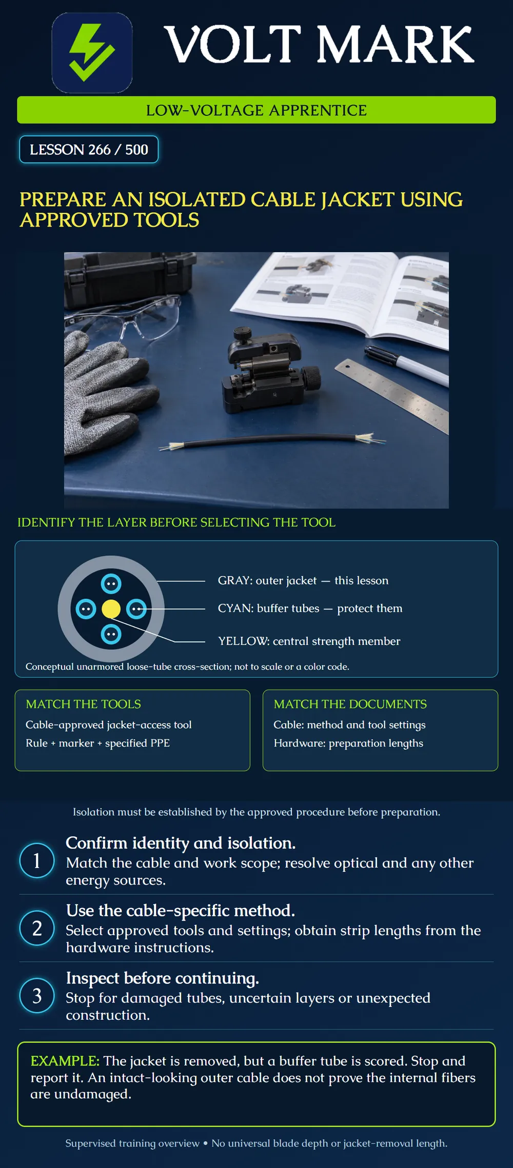
The poster depicts one conceptual unarmored loose-tube construction. Gray marks the outer jacket; cyan marks buffer tubes; the small white dots represent fibers; yellow marks a central strength member. The colors are teaching labels, not the industry fiber identification sequence. Layers are enlarged and simplified; binders, water-blocking materials and ripcords are omitted.
Jacket access exposes the protected internal construction. It is different from opening buffer tubes or stripping fiber coatings. Do not treat all three tasks as one cut. Actual cables may have armor, central tubes, ribbon assemblies, embedded strength members or a purpose-built access feature. Identify the actual product rather than forcing it to match this picture.
The cable procedure establishes the applicable access method and tool selection. The receiving enclosure or termination hardware establishes the preparation dimensions and routing needs. Keep both documents available and verify their applicability before marking the sample.
Corning's MiniXtend procedure, for example, identifies specific jacket-access tools, requires blade adjustment to avoid tube damage and ties jacket-removal length to the receiving hardware documentation. It separately addresses end access and mid-span access. Those procedures are not interchangeable. Its warning about confusing binder yarns with ripcords illustrates why internal components must be positively identified.
Record the approved tool model, cable range, blade condition and required setup procedure. A tool marketed for fiber may serve several layers, but that does not make one setting valid for every cable. Jonard's slit-and-ring tool description, for example, distinguishes cable support arrangements and adjustable cutting depth. That is evidence that tool configuration matters, not approval to substitute it for the tools in an unrelated cable procedure.
Where the applicable instructions require a setup check on matching scrap, perform that check under supervision before approaching the intended workpiece. Do not invent a blade depth from the outside diameter or use another technician's remembered setting. Never compensate for an uncertain setting by pressing harder.
Use the specified eye and hand protection and a stable, organized work area appropriate to the tools. Keep others outside the cutting path. Manage removed material and used blades according to the site procedure. Keep cable identification attached to the remaining workpiece, and protect internal components from contamination and unintended bending.
This lesson intentionally gives no generic cut sequence, strip length or blade-depth value. Perform the actual access operation only by following the exact cable and receiving-hardware instructions with the required supervision. Do not substitute a knife technique, heat, solvent or improvised tool for a missing approved method.
Before proceeding to the next preparation stage, look for the conditions identified by the applicable procedure, including unintended scoring, cuts, crushed or kinked tubes and an incorrect preparation boundary. Stop if the exposed construction differs from the expected cable description.
A visible defect is not fixed by hiding it beneath a sleeve or continuing the splice. Record the location and consult the authorized disposition process. Nor does an apparently neat jacket removal prove optical performance; required inspection and testing remain part of the broader work package.
A training worksheet identifies DEMO-LT cable and DEMO-H housing. The cable procedure names Tool A and a setup check; the housing drawing supplies the jacket-removal boundary. Three items appear on the bench: A matching tool with its current instructions. A similar-looking tool with an unreadable model label. A fiber-coating stripper intended for a later preparation stage.
Select the matching, verified tool for the jacket-access task. Hold the unidentified tool. Keep the coating stripper for its appropriate stage rather than using its presence as proof that the jacket task is ready.
The supervisor's sample has a score on a buffer tube after jacket removal. The correct exercise response is to stop, identify the defect and seek disposition. Do not decide that the fibers are unaffected merely because none are visible.
Cable identity / construction: Training isolation or authorized isolation record: Cable-access procedure / revision: Receiving-hardware procedure / revision: Approved tool and setup verification: Required preparation boundary: PPE and work-area check: Post-access inspection result: Defect / hold / supervisor disposition:
Mistake: Reusing a blade setting because the next cable has the same outside diameter. Correction: Match the exact cable construction and approved tool procedure, then perform the required supervised setup verification; outside diameter does not establish internal clearance.
Mistake: Choosing the fiber-coating stripper for jacket access because it is labeled for fiber work. Correction: Identify the preparation layer and use the tool specified for that layer. Keep jacket removal, buffer-tube access and coating stripping as separate tasks.
Mistake: Continuing after finding a scored buffer tube because no glass is exposed. Correction: Stop the next preparation stage, record the defect location and obtain the supervisor's disposition; hidden fibers are not evidence that damage is absent.
Corning, MiniXtend Loose Tube Cable Jacket and Buffer Tube Removal Procedures, SRP 004-197 Issue 3, August 2016: https://www.corning.com/catalog/coc/documents/standard-recommended-procedures/004-197.pdf Reference for distinctions between jacket/tube access, cable-specific tooling, adjustment, hardware-dependent preparation and internal-component identification. Product-specific strip lengths and cutting instructions are not generalized.
Jonard Tools, Cable Slit & Ring Tool: https://jonard.com/cable-slit-ring-tool?v=64 The product description identifies adjustable blade depth and cable-size support features. This lesson does not approve that tool as a substitute for Corning's named tools.
Texas journeyman, 15 questions, scored by topic against the 70% mark. No card, and no account needed to start.
Free study material for low-voltage apprentices. This is a national foundation course: requirements differ by state and by local jurisdiction, and a practice that is common in one place is not a rule everywhere. Nothing here is a licence, a certification, or authority to work unsupervised, and completing it does not count as apprenticeship hours or continuing-education credit. Check the codes adopted where you are working, the licensing authority for that work, and your employer's safety programme. VoltMark is not affiliated with, endorsed by, or sponsored by NFPA, OSHA, NICET, BICSI, FOA, or any state or local licensing authority.

Electrician licensing exam prep: practice questions, timed exam simulations, and step-by-step help finding every answer in the NEC.