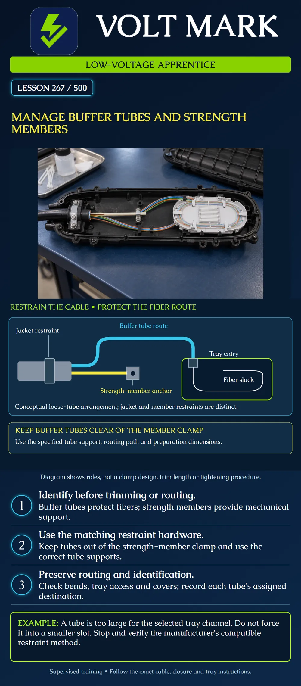
Identify the separate functions of buffer tubes and strength members, select the applicable restraint and routing instructions, and recognize a misrouted or mismatched component before continuing preparation.
Buffer tubes organize and protect the fibers they contain. Strength members provide mechanical support as part of the cable construction. The cable jacket, strength members and buffer tubes may each have distinct restraint arrangements in the receiving hardware. One clamp does not automatically perform every job.
The poster shows a conceptual loose-tube cable with a central strength member. Gray represents the jacket and hardware; yellow represents the central member; cyan represents a buffer tube; white represents fibers routed inside a tray. These are explanatory colors, not an identification code. Many cables use different constructions, including multiple strength elements or aramid yarn. Confirm the actual cable before selecting the method.
Use the exact cable preparation procedure, the receiving closure or enclosure instructions, and the selected tray instructions. Confirm that the hardware combination is intended for the cable construction and tube dimensions. Preparation length, anchor type, tightening requirements and routing sequence belong to those documents.
Corning's SCF-6/SCF-8 guide provides an example of a distinct central-member restraint and warns against trapping buffer tubes beneath it. It also directs tube slack to the designated storage area. That guide is product-specific and explicitly refers to the full instructions for installation details. This lesson does not transfer its torque values or trim dimensions to another enclosure.
Plan where each identified tube will enter its assigned tray. Check how the route fits the hardware's permitted service positions and how slack is supported. Do not shorten a tube or strength member merely because it appears longer than a nearby component.
The final route must satisfy the product's bend and support instructions without forcing the tube against a sharp edge or moving part. A tube can look tidy while still being compressed in an incorrect channel. An assembly can also fit with the tray open but become crowded when stacked or covered. Review the approved arrangement as a whole.
Use the specified tube-support method for the actual tube size and tray. Corning's M68-031 tray procedure, for example, warns that forcing a buffer tube into a smaller restraint position can collapse the tube and damage fibers. It also discusses alternate approved entry positions when routing would otherwise be too tight.
That historical product example demonstrates the need to match hardware. It does not establish a universal slot size, tie method, strip length or tray capacity. Obtain the applicable instructions for the equipment in the work package.
Identify the intended anchor and the relevant cable member. Keep the optical components clear of the mechanical connection. Use only the specified preparation and fastening procedure; do not invent a torque setting or cut the member flush before checking the hardware requirement.
A metallic member's electrical treatment is a separate design and installation consideration. A mechanical clamp is not automatically proof of a compliant bonding arrangement. Verify the approved requirements for the actual cable and enclosure without assuming that every fiber cable contains metal or that every metallic member uses the same method.
Preserve tube and fiber identification throughout preparation. Record the cable ID, tube ID and assigned tray or destination according to the project system. Do not rely on the diagram's cyan color as a real tube number. The next lesson covers applicable color sequences in detail.
Unused tubes or express fibers still require their specified protection and routing. Do not cut an unassigned tube on the assumption that it is unused. Resolve its documented service status first.
A training assembly has three findings:
All three are holds. Clear and reroute the first item only under the applicable supervised procedure. For the second, verify the compatible restraint method rather than compressing the tube. For the third, reconcile the records and labels before proceeding. Do not change the paperwork simply to match an unexplained physical arrangement.
The exercise is performed on a diagram or known isolated training sample. It does not authorize opening or moving installed live-service assemblies.
Confirm the approved cable identity and work status. Confirm the cable, enclosure and tray document revisions. Confirm the correct hardware for each restraint function. Confirm that tubes are clear of the member anchor. Confirm the intended tube routes, slack storage and permitted tray positions. Confirm that covers do not trap fibers. Record discrepancies and obtain the required disposition before continuing.
On the fictional assembly drawing, mark three HOLD callouts: the tube under the central-member cap, the tube that does not fit the selected restraint channel, and the T-03 destination disagreement. For each, write the evidence needed and the person who must resolve it. Do not manipulate hardware.
Expected response: For the trapped tube, identify the applicable enclosure routing instructions and request supervised correction plus inspection for damage. For the channel mismatch, confirm the actual tube size and the tray's compatible restraint method instead of squeezing it into place. For T-03, compare the approved tube-to-tray schedule with both labels and obtain an authorized resolution; neither record wins merely because it is easier to change. All three holds remain open until their dispositions are documented.
Mistake: Tightening the central-member cap with a buffer tube underneath because the member itself is correctly positioned. Correction: Stop fastening and use the applicable supervised routing procedure to keep optical components out of the anchor; inspect and report any suspected damage before continuing.
Mistake: Pressing an oversized tube into a smaller tray restraint to make the route look tidy. Correction: Check tube dimensions against the tray instructions and select the documented compatible restraint or entry arrangement; do not use compression as a fit adjustment.
Mistake: Changing T-03's schedule to Tray 3 simply because the physical training label says Tray 3. Correction: Record the conflict and reconcile the approved mapping with the responsible reviewer before changing labels or routing.
Corning, Quick Start Guide for SCF-6 and SCF-8 Canister Splice Closures, SRP 003-360-QSG Issue 3, November 2014: https://www.corning.com/catalog/coc/documents/standard-recommended-procedures/003-360-QSG.pdf Reference for the product-specific restraint and routing arrangement. Full installation details are in the product's main instructions, not this teaching overview.
Corning, Loading Splice Tray for Mechanical Splices (M68-031), SRP 001-240 Issue 4, March 2001: https://www.corning.com/catalog/coc/documents/standard-recommended-procedures/001-240.pdf Historical example supporting tube-size matching, compatible entry routing and avoiding fiber entrapment under covers. No current product availability or universal capacity asserted.
Texas journeyman, 15 questions, scored by topic against the 70% mark. No card, and no account needed to start.
Free study material for low-voltage apprentices. This is a national foundation course: requirements differ by state and by local jurisdiction, and a practice that is common in one place is not a rule everywhere. Nothing here is a licence, a certification, or authority to work unsupervised, and completing it does not count as apprenticeship hours or continuing-education credit. Check the codes adopted where you are working, the licensing authority for that work, and your employer's safety programme. VoltMark is not affiliated with, endorsed by, or sponsored by NFPA, OSHA, NICET, BICSI, FOA, or any state or local licensing authority.

Electrician licensing exam prep: practice questions, timed exam simulations, and step-by-step help finding every answer in the NEC.