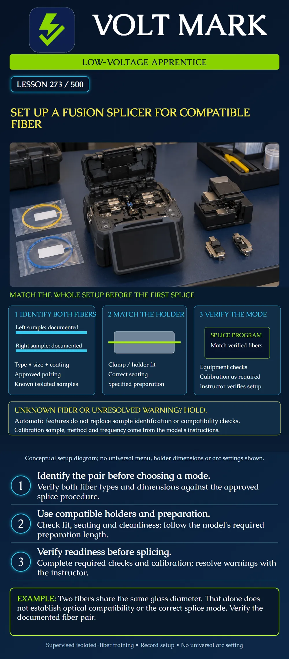
Build and verify a setup record for a supervised fusion-splicing exercise using known isolated training fibers. Explain why fiber identification, mechanical holding and the splice program must agree before the cycle starts.
Record the left and right sample identification separately. Obtain the fiber type, glass dimensions and coating or buffer details from the sample documentation. Color alone is not a complete optical specification. Equal outside glass diameter does not prove equal core characteristics or establish an approved pairing.
Confirm that the intended pair is within the exercise's approved procedure and the splicer's capabilities. A machine's ability to bring two pieces of glass together does not establish the intended link performance. Dissimilar-fiber splicing requires an appropriate engineered procedure; do not substitute it for a basic matching-fiber exercise.
This lesson is about setup. Performing the supervised training splice follows in lesson 274. Do not treat a completed worksheet as permission to work on a live service fiber.
Identify the exact splicer, cleaver, holder or sheath-clamp arrangement and relevant accessories. Use the compatible parts and preparation dimensions specified for that combination. A holder that looks similar is not automatically interchangeable.
AFL distinguishes a sheath clamp attached to the splicer from a removable fiber holder that can carry the fiber through preparation and into the machine. This distinction helps the apprentice recognize the equipment in front of them. It does not authorize removing or exchanging parts without the applicable instructions.
Confirm the supported coating or buffer arrangement and the correct seating of the approved holder. Record the preparation length and its reference point. Do not stretch, force or improvise packing around a sample to make it fit. Resolve unexpected movement before proceeding.
Use the isolated-sample and glass-scrap controls established in earlier lessons. Keep the workstation stable, clean and suitable for the actual equipment. Follow the manufacturer requirements for operating environment, power, covers, moving parts and hot surfaces.
The splicer produces an arc, and the protection-sleeve heater can be hot. Follow the equipment and cleaner precautions; do not bring unapproved flammable materials into the process. Keep cleaning liquid controlled and allow the required evaporation before the next operation.
Do not handle electrodes or perform improvised internal maintenance. Required cleaning, service or replacement must follow the model's safe maintenance procedure and the user's training.
Select the splice program prescribed for the identified fiber pair and process. Check the displayed choice rather than assuming yesterday's selection is still suitable. Record the choice and the instruction that supports it.
Automatic fiber-analysis and mode-selection features vary by machine. They are not a replacement for sample traceability in this exercise. If the sample is unknown, hold the exercise until the instructor resolves its identity or defines an approved identification procedure.
Keep splice mode and sleeve-heater mode conceptually separate. One controls the fiber-joining process; the other must suit the selected protection system. Confirm the appropriate protection and heater instructions before the later splice-protection step. No temperature or heating time is supplied here.
Perform the checks and calibration required by the actual model, mode, environment and procedure. Use the specified calibration fiber. Do not assume the fiber used for production or training is also the correct calibration sample.
AFL's 90S+ troubleshooting guide connects incorrect splice mode, preparation and equipment condition with errors. It calls for a particular reference fiber in its arc-calibration troubleshooting. That model-specific requirement must not be turned into a universal rule for every splicer. Record the required result and do not ignore an unresolved warning.
If a check fails, retain the error message and seek the instructor's next action. Do not lower rejection criteria, guess new arc parameters or repeatedly run cycles without investigating the cause. An automated adjustment is not evidence that every setup requirement was met.
Splicer model / asset ID / applicable manual revision: Left sample ID / type / glass and coating dimensions: Right sample ID / type / glass and coating dimensions: Approved pairing and procedure: Holder or clamp / cleaver / preparation reference: Splice program / reason selected: Required checks / calibration sample / result: Protection system and heater instructions: Unresolved warnings and disposition: Instructor readiness check:
A fictional setup sheet identifies both training samples and the approved splice program. The display matches that program, but the removable holder has a different identifier from the setup sheet and the required calibration result remains unresolved. The trainee proposes starting because the program is correct. The instructor keeps the exercise on HOLD. Program selection answers only one setup question. The holder must be verified against the approved configuration, and the calibration issue must be resolved using the model's specified sample and procedure. The record retains both open items and their dispositions. Only after all required checks are accepted may the next supervised step begin; no completed splice or link test is implied.
Mistake: Treating equal glass diameters as sufficient identification for selecting the splice program. Correction: Record both sample types and their documentation, then verify the approved pairing and matching program; hold an undocumented sample.
Mistake: Assuming a successful splice-program check also verifies the sleeve-heater setup. Correction: Check the protection system and its heater instructions separately and record the appropriate selections for both processes.
Mistake: Using the training fiber for calibration simply because it is already at the workstation. Correction: Identify the calibration sample specified for the actual model and procedure and resolve any mismatch before running that check.
AFL, Fusion Splicing Systems FAQs: https://www.aflglobal.com/en/resources/product-related-materials/frequently-asked-questions/fusion-splicing-systems Manufacturer reference for sheath-clamp versus removable-holder distinction and preparation/contamination context.
AFL, 90S+ Splicer Error Code and Troubleshooting Quick Guide, AN-3035, Revision 0, November 30, 2022: https://learn.aflglobal.com/_pfcdn/assets/preprocessed/11221/dbdf55c9-3246-42c1-9b9b-97f0610bab9b/dbdf55c9-3246-42c1-9b9b-97f0610bab9b.92e046c3-a933-447f-8e98-f44d65042f19 Manufacturer troubleshooting reference supporting mode, preparation, holder seating and calibration-related troubleshooting. No operational arc values or maintenance sequence generalized.
Texas journeyman, 15 questions, scored by topic against the 70% mark. No card, and no account needed to start.
Free study material for low-voltage apprentices. This is a national foundation course: requirements differ by state and by local jurisdiction, and a practice that is common in one place is not a rule everywhere. Nothing here is a licence, a certification, or authority to work unsupervised, and completing it does not count as apprenticeship hours or continuing-education credit. Check the codes adopted where you are working, the licensing authority for that work, and your employer's safety programme. VoltMark is not affiliated with, endorsed by, or sponsored by NFPA, OSHA, NICET, BICSI, FOA, or any state or local licensing authority.

Electrician licensing exam prep: practice questions, timed exam simulations, and step-by-step help finding every answer in the NEC.