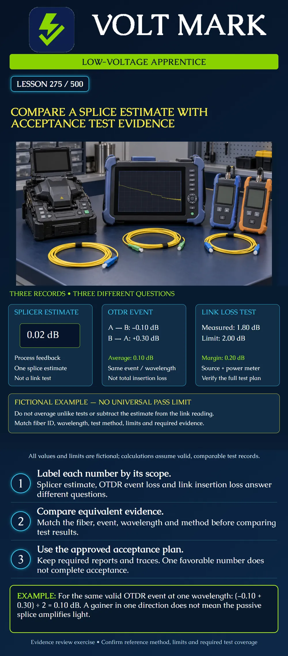
Sort three kinds of loss information correctly: the splicer's estimate, an OTDR event result, and an end-to-end insertion-loss measurement. Review the evidence against a defined acceptance plan without treating unlike numbers as interchangeable.
Before comparing numbers, identify what each record describes. “Loss: 0.02 dB” is incomplete without an instrument, method, sample identity and scope. A small value may be useful process feedback while proving nothing about the rest of a link.
A splicer generally reports an estimate for the joint it has just made. Preserve that estimate with the splice record and any warnings. Do not rewrite its label as a certified link measurement. The FOA fusion-splicing reference explicitly distinguishes the machine estimate from subsequent testing.
An optical time-domain reflectometer, or OTDR, provides information along the fiber and can characterize a splice event. Its result depends on appropriate setup, event resolution and interpretation. A particular event may be difficult to separate from a nearby connector or other event. Do not invent a standalone splice value when the trace cannot resolve it.
An optical loss test set, or an appropriate light source and power meter, measures insertion loss over the defined test path. Its result depends on a valid reference and the specified method. This total does not identify how much loss belongs to each individual splice.
Confirm that each record belongs to the intended fiber. Record endpoints, wavelength, instrument and test method. For an OTDR comparison, locate the same physical event in both directions; its distance from the launch end changes when the test direction changes.
Do not average different wavelengths, different fibers or different events. Do not substitute a nearby trace because its number looks better. An unlabeled screenshot is weak evidence even if it displays a favorable result.
Different backscatter characteristics across a joint can produce apparent gain in one direction and exaggerated loss in the other. Appropriate bidirectional testing and averaging of the matching event improve the estimate of that event's loss. A negative event reading does not mean the passive splice creates optical power.
This is not permission to average invalid traces. The event must be identifiable, measurements must be suitable, and the method must follow the equipment and project instructions. Preserve the underlying traces, not only the final arithmetic.
Assume a fictional training record for the same splice at 1310 nm contains: Splicer estimate: 0.02 dB. OTDR A-to-B event loss: -0.10 dB. OTDR B-to-A event loss: +0.30 dB. Assume both traces validly resolve the same event.
Average event result = (-0.10 + 0.30) / 2 = 0.10 dB. Do not average 0.02, -0.10 and +0.30 together. The splicer estimate is not a third directional OTDR measurement.
A separate valid insertion-loss report for the complete fictional test path at 1310 nm reads 1.80 dB. Its exercise limit is 2.00 dB. Arithmetic margin = 2.00 - 1.80 = 0.20 dB.
That meets this one stated numerical comparison. It does not prove all acceptance requirements were satisfied. The exercise supplies no splice-event acceptance limit, so the 0.10 dB event result cannot independently be declared passing. Required additional wavelengths, directions, polarity, length, reflectance or other project criteria still need their specified evidence.
Do not subtract 0.02 dB from 1.80 dB to “correct” the link measurement. Do not replace a measured result with the estimate. Both numbers retain their own meaning.
Obtain the approved limits and required coverage before deciding acceptance. The plan should define the tested path, reference method, wavelengths, applicable directions and required deliverables. Confirm the selected limit matches the intended test scope.
A missing required result is an incomplete record, not a zero-loss result. An incorrect reference or mismatched test setup requires correction and valid retesting; a favorable displayed PASS does not cure the setup problem. Follow the applicable rules for borderline results and measurement uncertainty rather than inventing a rounding allowance.
Fiber ID / endpoints: Splice location / identifier: Splicer estimate and warnings: OTDR event IDs / wavelengths / directions / trace filenames: Event averaging method and result: Insertion-loss report / reference method / wavelength: Applicable limits and source: Missing or invalid evidence: Reviewer disposition / required corrective action:
Mistake: Averaging the splicer's estimate with both directional OTDR readings because all three use dB. Correction: Keep the estimate separate and average only valid matching directional event measurements under the specified method; label each result by instrument and scope.
Mistake: Pairing events at the same distance from the launch end when reversing direction. Correction: Use the fiber identity, endpoints and physical splice location to match the event across traces; its distance from the launch end changes with direction.
Mistake: Declaring the splice acceptable because the complete path has positive insertion-loss margin. Correction: Check the separate event limit and other required evidence in the acceptance plan; mark an absent criterion or result unresolved rather than borrowing the link limit.
Fluke Networks, OLTS & OTDR: A Complete Testing Strategy: https://www.flukenetworks.com/edocs/olts-otdr-complete-testing-strategy Manufacturer guidance for complementary test scopes, reference-method significance and matching directional event evaluation. No blanket national test limit asserted.
Fluke Networks, Troubleshooting Fusion Splices, December 13, 2017: https://www.flukenetworks.com/blog/cabling-chronicles/troubleshooting-fusion-splices Manufacturer guidance for backscatter-related gain/loss artifacts and event-detection limitations. Historical product default settings were not adopted.
FOA, Fusion Splicing: https://www.thefoa.org/tech/ref/termination/fusion.html Educational reference for the machine-estimate versus testing distinction.
Texas journeyman, 15 questions, scored by topic against the 70% mark. No card, and no account needed to start.
Free study material for low-voltage apprentices. This is a national foundation course: requirements differ by state and by local jurisdiction, and a practice that is common in one place is not a rule everywhere. Nothing here is a licence, a certification, or authority to work unsupervised, and completing it does not count as apprenticeship hours or continuing-education credit. Check the codes adopted where you are working, the licensing authority for that work, and your employer's safety programme. VoltMark is not affiliated with, endorsed by, or sponsored by NFPA, OSHA, NICET, BICSI, FOA, or any state or local licensing authority.

Electrician licensing exam prep: practice questions, timed exam simulations, and step-by-step help finding every answer in the NEC.