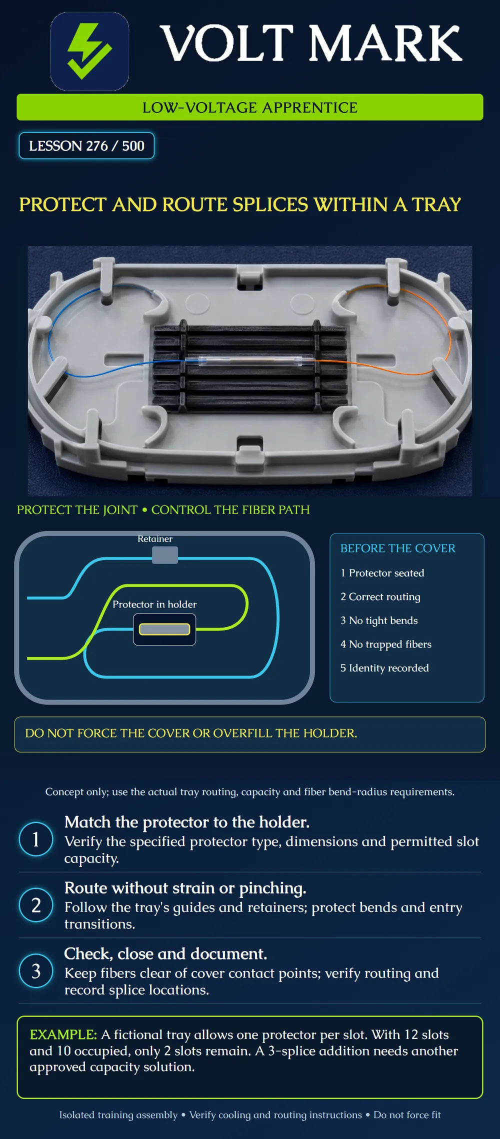
Review a protected training splice and its route through a compatible tray. Recognize capacity, strain and cover-clearance problems before the assembly is closed.
A successful joining operation does not finish fiber management. The protected joint must occupy its intended holder, and the surrounding fiber must follow a suitable route. A tidy-looking assembly can still have an incorrect protector, excessive bend or trapped fiber.
The poster is an original conceptual illustration, not a template to copy into a real product. Cyan and lime distinguish the two sides of one teaching splice. They do not specify a fiber color code. The gray element represents a retainer; the small central sleeve represents the protected joint. Dimensions and entry locations are intentionally unspecified.
Corning's SRP 001-284 describes particular trays and calls for using the related cable, splicing-component and hardware instructions together. It distinguishes entry configurations, plans fiber routing before splicing, seats protected splices in an organizer and keeps fibers beneath the intended retention features before fitting the cover. Capacity and routing details apply to the identified products, not every tray.
Use the exact tray and protector identification to verify compatibility, permitted occupancy and the appropriate routing drawing. Do not turn a product-specific double-stacking allowance into a general rule. Required slack, loop count, preparation lengths and fastening methods also depend on the assembly.
For the isolated training assembly, list the tray, holder and protector part numbers. Attach or identify the applicable instruction revision. Record the actual fiber pair and planned slot. Have the instructor resolve missing data before handling or rearranging the assembly.
Confirm completion of the specified protector process and cooling before storage. Maintain the required eye protection and scrap controls. Do not reach into or rearrange an in-service closure as an extension of this training exercise.
Trace each training fiber from its entry to its assigned splice. Compare that path with the product's routing instructions and the applicable fiber limits. Check local transitions as well as the broad storage curve. A broad loop elsewhere does not cancel a tight corner near the holder.
Check that retention features serve their intended purpose without crushing or trapping the fiber. Treat unexpected cover resistance as a reason to stop and inspect. A cover is not a press for making an overfilled tray fit.
Keep the splice identification and routing record consistent with the physical arrangement. When a rework decision changes the slot or available slack, update the record and reassess the route.
Assume a fictional training tray has 12 approved slots and its instructions permit exactly one protector per slot. Ten slots are occupied. Remaining capacity = 12 - 10 = 2 protectors. A proposed addition contains three new splices. Required occupancy = 10 + 3 = 13 protectors. Shortfall = 13 - 12 = 1 approved slot.
The proposal exceeds the fictional capacity. Do not double-stack merely because another manufacturer's tray allows it. The instructor must choose an approved capacity solution. The exercise does not specify which additional tray or enclosure is suitable.
If the same tray instead had eight occupied slots, four would remain. Three additions would fit the occupancy count, leaving one slot. That arithmetic alone would not verify the protector dimensions, routing, enclosure capacity or future access.
Tray / holder / protector identified: Permitted occupancy verified: Protected joint seated in planned position: Routing matches the applicable drawing: Local bends and transitions checked: Retention features used correctly: No fiber in cover contact areas: Cover fits by its specified method without forcing: Labels and splice record agree: Required inspection or retesting completed:
A fictional tray permits one protector in each of 12 approved slots. Ten slots are occupied and three new splices are proposed. The reviewer calculates two available slots and a one-slot shortfall, so the proposal is held. Putting two protectors in one slot would contradict this exercise's instructions even if the cover appeared to fit. The instructor must select an approved capacity arrangement and verify its enclosure compatibility. After that decision, the route, protector fit, retention features and cover clearance still need inspection. Counting enough slots is one check, not proof that the assembly is ready to close.
Mistake: Double-stacking protectors because the lid still fits and another tray permits it. Correction: Verify permitted occupancy for the exact tray and protector combination; hold additions beyond that capacity for an approved solution.
Mistake: Pulling a fiber tight to reach the slot shown on the original worksheet. Correction: Hold the assembly for an approved routing or rework decision, then update the slot record and recheck slack and local bends.
Mistake: Pressing down a resistant cover to finish a neat-looking tray. Correction: Stop closure and inspect the route and cover contact areas against the actual instructions; resolve trapped fiber or overfill before fitting the cover by its specified method.
Corning, Splice Trays Using Heat-Shrink Splice Protectors, SRP 001-284-AEN, Issue 7, April 2021: https://www.corning.com/catalog/coc/documents/standard-recommended-procedures/001-284.pdf Manufacturer reference covering routing, organizer and cover requirements. Product-specific lengths, crimp settings and stacking details were not generalized. The extracted materials section has confusing single-fiber/ribbon wording; no purchasing part-number recommendation is derived from it.
Texas journeyman, 15 questions, scored by topic against the 70% mark. No card, and no account needed to start.
Free study material for low-voltage apprentices. This is a national foundation course: requirements differ by state and by local jurisdiction, and a practice that is common in one place is not a rule everywhere. Nothing here is a licence, a certification, or authority to work unsupervised, and completing it does not count as apprenticeship hours or continuing-education credit. Check the codes adopted where you are working, the licensing authority for that work, and your employer's safety programme. VoltMark is not affiliated with, endorsed by, or sponsored by NFPA, OSHA, NICET, BICSI, FOA, or any state or local licensing authority.

Electrician licensing exam prep: practice questions, timed exam simulations, and step-by-step help finding every answer in the NEC.