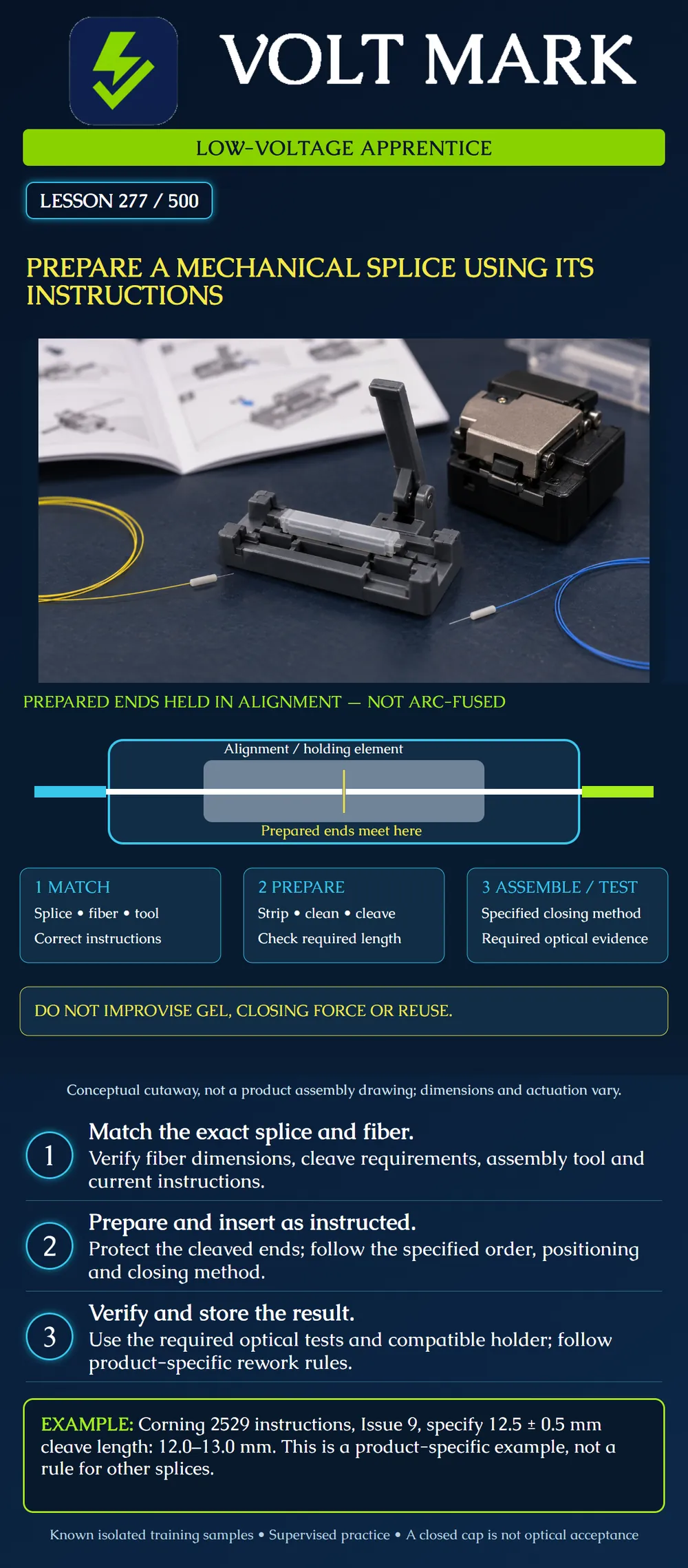
Use a mechanical splice's own instructions to plan a supervised training assembly, check preparation and identify the evidence required after assembly.
A mechanical splice holds prepared fiber ends in alignment rather than welding them with an arc. The drawing separates that principle from any particular product. It is not a dimensional cutaway or a hand-placement guide.
Some products incorporate index-matching material. Do not assume that material is a user-added adhesive, and do not add an unidentified liquid or gel to improve a result. The product instructions govern its use and handling.
Corning's Fibrlok family brochure distinguishes splice variants, compatible preparation and application tools. Similar-looking products do not necessarily share the same cleave or tool requirements. Mechanical fit also does not establish that an arbitrary optical fiber pair is appropriate for the planned application.
Identify the exact splice and instruction revision. Record both sample IDs, their fiber and coating dimensions, the assembly tool and cleaver, and the compatible storage holder. Confirm that these known training samples are isolated from optical sources.
Use the clean workstation, required eye protection and controlled glass-scrap collection established in earlier lessons. Follow the applicable cleaner and product safety information. Ask the instructor to demonstrate the actual tool before assembly.
A packaging label or family brochure can help identify the product, but it does not replace the full installation instructions. Resolve missing or conflicting identification before beginning.
Locate the preparation dimensions and their reference points. Distinguish coating removal length from the required cleaved glass length. Find the prescribed insertion order, positioning indicators, closing operation and corrective-action instructions.
Corning's 2529 procedure, Issue 9, gives a 12.5 ± 0.5 mm cleave length and tells the operator not to wipe the fiber again after cleaving. It also has specific insertion and actuation instructions, prohibits treating the splice as tunable, and distinguishes permitted repositioning from removal and reuse. Those details belong to that product and revision.
This lesson does not reproduce its hand technique or provide a universal insertion force. Use the actual manufacturer's procedure with the instructor. If the required indication is absent, stop and follow its corrective action rather than pushing harder.
Using the cited 2529 requirement solely as a reading exercise: Nominal length = 12.5 mm. Tolerance = 0.5 mm. Lower endpoint = 12.5 - 0.5 = 12.0 mm. Upper endpoint = 12.5 + 0.5 = 13.0 mm.
A recorded 12.4 mm lies within this dimensional interval. A recorded 13.2 mm exceeds the upper endpoint by 0.2 mm. Neither arithmetic statement verifies surface quality, fiber identity or completed assembly performance. Actual measurement uncertainty and the approved checking method still matter.
Do not transfer this interval to another mechanical splice or a field-termination connector. Obtain that product's required length separately.
Handle the sample as instructed without contaminating its prepared end. If preparation is compromised, use the approved re-preparation process. Keep cut fragments contained and away from the splice and work surface.
Confirm the required position before operating the closure mechanism. A cap that appears closed is only a mechanical observation. Do not label it an optical pass.
Apply the exercise's required optical test method and limits. Preserve the sample ID, result and any rework. A product's typical performance value is not automatically the acceptance limit for a particular job.
Store the completed splice in an approved holder and follow the routing principles from lesson 276. A holder intended for a different protector is not acceptable merely because the body can be wedged into it.
Splice identification / instruction revision: Left and right sample IDs / dimensions: Approved fiber pairing: Assembly tool / cleaver / preparation requirement: Observed preparation and position: Actuation result / abnormalities: Required test method / limit / result: Rework authorization and outcome: Holder and storage position: Instructor check:
For the cited 2529 reading exercise, a trainee records a 13.2 mm cleave and says the closed cap proves assembly is acceptable. The reviewer calculates the specified upper endpoint as 12.5 + 0.5 = 13.0 mm. The recorded length exceeds it by 0.2 mm, so closing the cap cannot resolve that preparation discrepancy. The instructor holds the sample and selects the corrective action from the applicable instructions. Any rework must respect the product's removal and reuse restrictions. After approved preparation and assembly, required optical evidence is still needed; a dimension within tolerance would not itself prove optical performance.
Mistake: Using the 2529 cleave interval on another mechanical splice because both bodies look similar. Correction: Identify the actual product and revision, then read its preparation length and reference point before setting up the cleaver.
Mistake: Treating permission to reposition installed fibers as permission to remove them and reuse the splice body. Correction: Read the separate repositioning and reuse rules; obtain the specified replacement when the product requires a new splice.
Mistake: Calling the sample an optical pass when its cap closes normally. Correction: Record closure as an assembly observation and obtain the required optical test result against the stated limit before acceptance.
Corning, Fibrlok Splices, CRR-919-AEN, January 2019: https://www.corning.com/catalog/coc/documents/brochures/CRR-919-AEN.pdf Manufacturer brochure reference for operating principle and product-family distinctions. No broad marketing language interpreted as approval to join arbitrary fiber types.
Corning, Fibrlok II Universal Optical Fiber Splice 2529, SRP 78-8128-0163-3, Issue 9, October 2019: https://aselcom.com/Anexos%20PS/Manuales/H78-8128-0163-3-9.pdf Manufacturer-authored manual hosted by a third party. Product identity and revision must be checked against the actual kit before practical use; this lesson does not claim the hosted copy is the latest revision.
Texas journeyman, 15 questions, scored by topic against the 70% mark. No card, and no account needed to start.
Free study material for low-voltage apprentices. This is a national foundation course: requirements differ by state and by local jurisdiction, and a practice that is common in one place is not a rule everywhere. Nothing here is a licence, a certification, or authority to work unsupervised, and completing it does not count as apprenticeship hours or continuing-education credit. Check the codes adopted where you are working, the licensing authority for that work, and your employer's safety programme. VoltMark is not affiliated with, endorsed by, or sponsored by NFPA, OSHA, NICET, BICSI, FOA, or any state or local licensing authority.

Electrician licensing exam prep: practice questions, timed exam simulations, and step-by-step help finding every answer in the NEC.