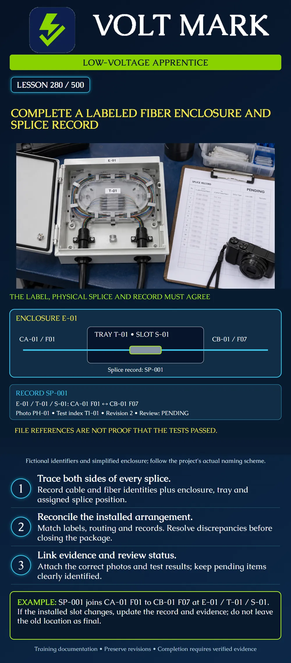
Create a consistent record of a training enclosure that connects physical labels, splice identities, storage positions and evidence. Identify what remains incomplete before presenting the package for review.
A splice record should allow another trained person to find the intended joint without guessing from color or appearance. Identify both cables and both fibers, then identify where the joint is stored. A fiber color can repeat across tubes, ribbons and cables; it is not a complete identifier by itself.
FOA's documentation guidance connects cable locations, fiber paths, interconnections and test results. Its deliverables guidance emphasizes understandable records and knowledgeable review of test evidence. This lesson turns those principles into an original small training exercise, not a universal naming standard.
Enclosure: E-01. Tray: T-01. Position: S-01. Splice record: SP-001. Side A: cable CA-01, fiber F01. Side B: cable CB-01, fiber F07. Photo reference: PH-01. Test evidence index: TI-01. Record revision: 2. Review status: PENDING.
The diagram and record deliberately repeat the same mapping. The two fiber numbers are different; matching numbers are not required when the approved design calls for this pairing. Do not change F07 to F01 merely to make a row look symmetrical.
F01 and F07 here are fictional global fiber identifiers within their respective cables. A real project may also require tube, ribbon or subunit fields. Use the actual naming convention and preserve its hierarchy.
On the known isolated training assembly, check labels against the approved plan and actual arrangement. Verify enclosure, cable-entry and tray identification. Trace the two identified fibers to the intended protected splice and slot under the instructor's supervision.
Follow the enclosure manufacturer's instructions for cable restraint, compatible trays, routing, covers and closure. Do not use a documentation exercise as permission to open a live service enclosure. A photograph cannot prove hidden restraints, seals or routing conditions unless the relevant inspection was actually performed.
Place labels using suitable materials and approved locations. Avoid obstructing latches, service information, inspection access or moving components. Do not attach improvised labels directly to fragile glass. Keep identifiers readable after the enclosure is returned to its intended configuration.
Each row should identify a real planned or installed relationship. Distinguish those states explicitly. Record the splice method, position, date, responsible person and applicable revision where the project requires them.
Include unused, reserved or express fibers according to the design. An empty cell is ambiguous: it could mean unused, unknown, omitted or not checked. Use defined status terms instead of guessing.
For a correction, retain enough history to explain what changed and why. Mark superseded drawings so they cannot be mistaken for the current configuration. Do not silently relabel a test file to make it fit an incorrect splice record.
PH-01 is a reference to a photograph, not proof that the photograph exists or shows the correct assembly. Open it and verify the identity, viewpoint and final condition. Likewise, TI-01 must point to actual test records covering the required fibers, methods, wavelengths and directions.
Keep splicer estimates separate from optical acceptance reports, as taught in lesson 275. A folder containing many files can still omit one required fiber or contain duplicate results assigned to different identifiers.
Record the inspection and testing status honestly. The poster shows PENDING because no actual test evidence is supplied for the fictional enclosure. Do not replace that with PASS simply because the fields are filled.
Assume a training package expects six installed splice rows. Five rows match the physical assembly; the sixth lists the wrong tray. The package has six rows, but only five reconciled mappings. Correct and recheck the sixth before calling the mapping complete.
Now suppose six report references exist but two point to the same test file for one fiber. Count alone is insufficient. Resolve whether a required result is missing or a reference was duplicated; do not fabricate a second report.
If SP-001 moves from S-01 to S-03 during approved rework, update the current location, photo and relevant final-condition evidence. Preserve the prior revision as superseded. The splice's logical fiber pairing may remain unchanged while its physical position changes.
Enclosure ID and location: Cable entries and cable IDs: Tray IDs and capacity verified: Splice rows matched to both fiber identities: Storage positions matched: Unused / express / reserved fibers recorded: Labels and current drawing agree: Photos opened and checked: Required test files opened and checked: Missing items / discrepancies: Current revision / superseded records: Qualified reviewer and disposition:
Mistake: Changing Side B from F07 to F01 so the splice row looks symmetrical with Side A. Correction: Preserve the approved CA-01/F01 to CB-01/F07 pairing and reconcile each side to its own cable and fiber identity.
Mistake: Declaring six fibers tested because six report references are filled in. Correction: Open each referenced result, match its fiber and required test coverage, and resolve duplicates or missing evidence before recording completion.
Mistake: Moving SP-001 to S-03 during rework while retaining the S-01 photo and worksheet as current. Correction: Update the physical position and final-condition evidence together, retain the prior revision as superseded, and recheck that labels and records agree.
FOA, Outside Plant Fiber Optic Network Design: https://www.thefoa.org/tech/ref/OSP/design.html Educational reference whose documentation section supports cable/fiber identification, paths and test records. No nationwide identifier format imposed.
FOA, Fiber Optic Installation Deliverables: https://www.thefoa.org/tech/ref/install/deliverables.html Educational reference for understandable deliverables and knowledgeable verification of test records. Numerical performance recommendations from that page are not adopted as universal requirements.
Corning, SRP 001-284-AEN, Issue 7: https://www.corning.com/catalog/coc/documents/standard-recommended-procedures/001-284.pdf Product-specific tray routing and cover instructions remain applicable only to the identified hardware.
Texas journeyman, 15 questions, scored by topic against the 70% mark. No card, and no account needed to start.
Free study material for low-voltage apprentices. This is a national foundation course: requirements differ by state and by local jurisdiction, and a practice that is common in one place is not a rule everywhere. Nothing here is a licence, a certification, or authority to work unsupervised, and completing it does not count as apprenticeship hours or continuing-education credit. Check the codes adopted where you are working, the licensing authority for that work, and your employer's safety programme. VoltMark is not affiliated with, endorsed by, or sponsored by NFPA, OSHA, NICET, BICSI, FOA, or any state or local licensing authority.

Electrician licensing exam prep: practice questions, timed exam simulations, and step-by-step help finding every answer in the NEC.