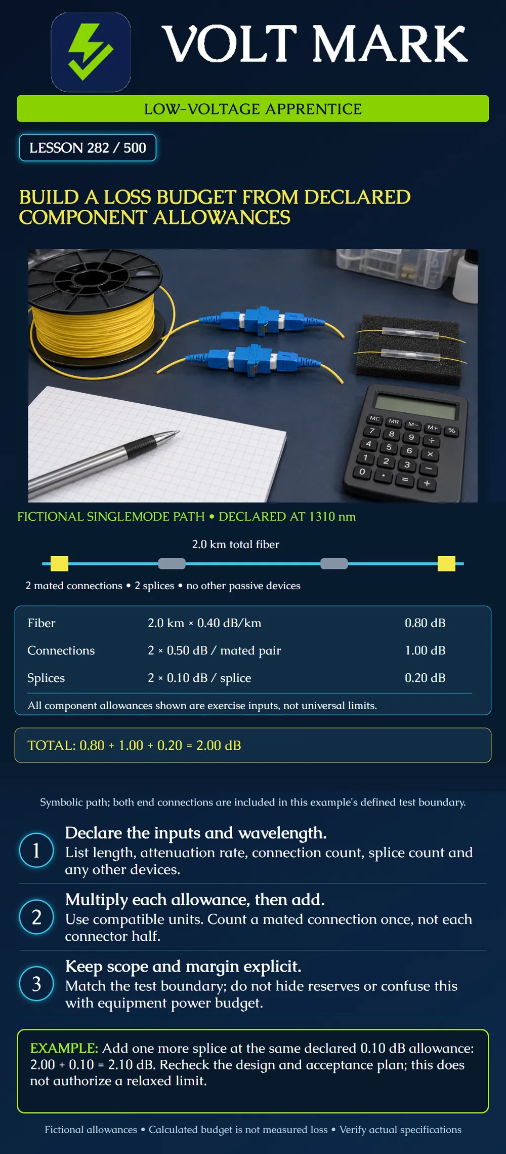
Calculate a fiber-path loss budget from explicitly stated component allowances, preserve its wavelength and boundary, and distinguish the result from a measurement or equipment power budget.
Use the acceptance-plan scope from lesson 281. Identify which fiber length, connections, splices and passive devices lie inside the calculation boundary. Match that boundary to the intended test method. Do not omit an included component or count an excluded connection simply because it appears on a drawing.
FOA's loss-budget guidance distinguishes the passive cable-plant estimate from the equipment power budget. It adds the contributions of fiber, connections, splices and other passive devices, while emphasizing wavelength and reference-method scope. This lesson uses an original fictional path to practice that arithmetic.
For each allowance, record its source, units, wavelength and applicability. Use the approved design specifications and actual products for real work. Do not mix a typical value for one part with a maximum requirement for another without identifying and justifying the basis.
Fiber attenuation is commonly expressed in dB per kilometer. Convert the relevant total fiber length to kilometers before multiplying. Include the length required by the defined path, not merely a straight-line map distance.
For this exercise, a connection allowance describes one mated connector pair. Count each such joint once. A splice is another separately counted joint. Additional passive devices, if present, require their own applicable loss contributions.
Assume a fictional singlemode path at 1310 nm: Total fiber length within scope: 2.0 km. Declared fiber attenuation allowance: 0.40 dB/km. Mated connections within scope: 2. Declared allowance per mated connection: 0.50 dB. Splices within scope: 2. Declared allowance per splice: 0.10 dB. Other passive devices: none.
Fiber contribution = 2.0 km × 0.40 dB/km = 0.80 dB. Connection contribution = 2 × 0.50 dB = 1.00 dB. Splice contribution = 2 × 0.10 dB = 0.20 dB. Calculated total = 0.80 + 1.00 + 0.20 = 2.00 dB.
Both end connections are included in this fictional boundary. The diagram's spacing does not represent physical distances between events. Its two gray sleeves represent the two counted splices; yellow blocks represent the two counted mated connections.
All rates and allowances are declared training inputs. The result is not a national limit, a code requirement or proof of actual installed performance.
If the same length were given as 2,000 m, first convert: 2,000 m ÷ 1,000 m/km = 2.0 km. Using 2,000 directly with dB/km would produce a thousandfold length error.
Do not count the two halves of each mating connection as two separate 0.50 dB allowances. In this example there are two mated joints, contributing 1.00 dB in total.
Do not add optical power readings in dBm to these loss allowances in dB. Loss contributions along a passive path may be added in dB; an absolute power reading has a different meaning.
If the project requires a reserve for future repairs or another design margin, state its purpose and value explicitly. Do not hide it inside a component count. Do not assume such a reserve increases the allowable measured installation loss.
The calculated total must be checked against application and equipment requirements as well as the agreed test criteria. Lesson 283 develops the equipment comparison. A favorable arithmetic total alone does not establish bandwidth, distance, reflectance or other application compliance.
A measured result near a criterion must be evaluated using the agreed decision rule and valid setup. Do not invent a tolerance after testing. Retain input revisions so the budget can be reproduced.
Path ID / boundary / reference method: Wavelength / fiber type: Fiber length and units: Attenuation allowance and source: Mated-connection count / allowance / source: Splice count / allowance / source: Other passive devices and contributions: Calculated component total: Separately declared reserves and purpose: Application comparison / approved test criteria: Revision / reviewer / unresolved inputs:
Mistake: Multiplying 2,000 meters directly by an allowance stated in dB per kilometer. Correction: Convert the length to 2.0 kilometers first, then multiply by the wavelength-specific attenuation allowance and retain the units in the calculation.
Mistake: Counting both connector halves as separate mated-connection allowances. Correction: Mark each included mating joint on the defined path and apply one declared pair allowance per joint; the example has two joints, not four.
Mistake: Increasing the measured acceptance limit automatically when a new splice raises the calculated budget. Correction: Record the revised component total, then obtain the required design and acceptance-plan review; a changed estimate does not authorize a changed test limit.
FOA, Calculating Fiber Optic Loss Budgets: https://www.thefoa.org/tech/lossbudg.htm Educational reference for additive component budgeting, boundary/reference awareness and power-budget distinction. Numerical inputs and all change exercises here are original declared examples; historical generic limits from the source are not presented as current universal requirements.
Texas journeyman, 15 questions, scored by topic against the 70% mark. No card, and no account needed to start.
Free study material for low-voltage apprentices. This is a national foundation course: requirements differ by state and by local jurisdiction, and a practice that is common in one place is not a rule everywhere. Nothing here is a licence, a certification, or authority to work unsupervised, and completing it does not count as apprenticeship hours or continuing-education credit. Check the codes adopted where you are working, the licensing authority for that work, and your employer's safety programme. VoltMark is not affiliated with, endorsed by, or sponsored by NFPA, OSHA, NICET, BICSI, FOA, or any state or local licensing authority.

Electrician licensing exam prep: practice questions, timed exam simulations, and step-by-step help finding every answer in the NEC.