Compare compatible transmitter and receiver specifications with a cabling loss budget, and recognize why both insufficient power and excessive received power must be checked.
The cabling loss budget from lesson 282 estimates passive-path loss from declared component allowances. The equipment power budget describes the power difference available between a transmitter and the receiver's required input under specified conditions.
FOA's loss-budget reference distinguishes these concepts and explains that application impairments may reduce usable allowance. Cisco's historical optical installation guidance likewise distinguishes budget, loss and margin, and discusses receiver overload. The principles support this exercise; its numbers are fictional and are not specifications for any Cisco product.
Identify the exact transmitter, receiver, fiber, wavelength, data rate and supported configuration. Verify both equipment directions. A supported pair may still have different values in each direction.
Use comparable power definitions. Do not subtract an average-power transmitter value from an optical-modulation-amplitude sensitivity value as though they were interchangeable. Conditions such as coding, FEC, temperature and specified error rate can matter.
Record the manufacturer's application channel-loss limit where provided. A simple transmit-minus-sensitivity calculation does not override that limit, distance restrictions, dispersion requirements, reflectance limits or host compatibility.
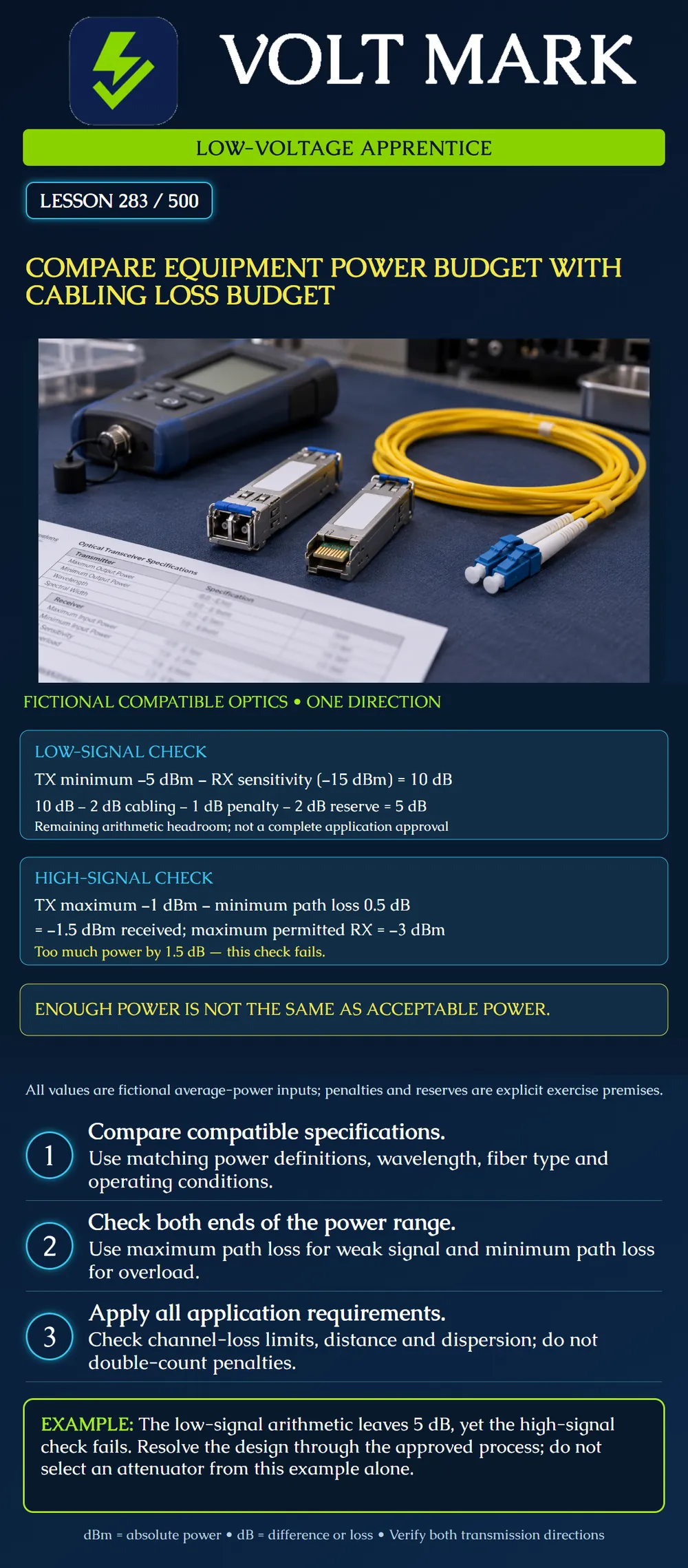
Assume compatible fictional optics with average optical power specifications: Minimum transmitter output: -5 dBm. Receiver sensitivity: -15 dBm. Maximum planned cabling loss: 2 dB. Separately required impairment penalty: 1 dB. Separately required design reserve: 2 dB.
Raw power difference = -5 - (-15) = 10 dB. Remaining arithmetic headroom = 10 - 2 - 1 - 2 = 5 dB.
The 1 dB penalty and 2 dB reserve are explicit exercise premises, assumed not already included in the other values. Real specifications may already include relevant penalties. Do not subtract the same item twice.
Predicted minimum received average power before the separate penalty/reserve deductions is -5 dBm - 2 dB = -7 dBm. That is 8 dB above the stated sensitivity. After allowing the separate 3 dB deductions, the exercise leaves 5 dB. This does not complete application approval.
For the same fictional direction, assume: Maximum transmitter output: -1 dBm. Minimum possible path loss: 0.5 dB. Maximum permitted receiver input for operation: -3 dBm.
Predicted maximum received power = -1 - 0.5 = -1.5 dBm. Because -1.5 dBm is greater than -3 dBm, the input is too high. Excess above the permitted level = -1.5 - (-3) = 1.5 dB.
The low-signal comparison was favorable, but this high-signal comparison fails. The 2 dB maximum cabling allowance from the first calculation cannot substitute for the 0.5 dB minimum path loss here. An upper bound does not prove a lower bound.
The 1.5 dB excess is an arithmetic result, not a complete attenuator specification. A real corrective design must consider tolerance, wavelength, connector compatibility, minimum and maximum received power, application limits and any required margin. Recheck the weak-signal case after adding loss.
Do not deliberately bend the cable, contaminate a connector or create a poor splice to reduce received power. Use only the approved design and suitable components.
Receiver overload is also distinct from an absolute damage threshold. Use the correct operating limit and do not assume a receiver is safe merely because an unrelated damage rating is higher.
Equipment pair / supported configuration: Direction / wavelength / power definition: Minimum TX / receiver sensitivity: Maximum TX / maximum operating RX: Maximum and minimum path loss: Application channel-loss limit: Included and separately required penalties: Design reserves and purpose: Weak-signal calculation: Overload calculation: Other application checks: Required corrective design / reviewer:
Mistake: Using maximum cabling loss for both the weak-signal and receiver-overload calculations. Correction: Check minimum transmitter power with maximum path loss for weak signal, and maximum transmitter power with minimum path loss for overload, using the applicable equipment definitions.
Mistake: Subtracting a separate impairment penalty even though the published application limit already includes it. Correction: Record which penalties are included in each specification and subtract only separately required items once on a consistent basis.
Mistake: Ordering a 1.5 dB attenuator solely from the fictional overload excess. Correction: Refer the corrective design for review of tolerance, wavelength, interfaces and both receiver power extremes; the arithmetic excess alone is not a component specification.
FOA, Calculating Fiber Optic Loss Budgets: https://www.thefoa.org/tech/lossbudg.htm Educational reference supporting power/loss-budget distinction and application-impairment context.
Cisco, ATM Network Modules, revised May 1, 2008: https://www.cisco.com/c/en/us/td/docs/routers/access/interfaces/nm/hardware/installation/guide/ConntATM.html Relevant sections: Power Budget and Power Margin, and Single-Mode Transmission. Historical equipment values and attenuator recommendations are not generalized. The source contains inconsistent dB/dBm labels in parts of its example; this lesson explicitly uses dBm for absolute power and dB for differences.
Texas journeyman, 15 questions, scored by topic against the 70% mark. No card, and no account needed to start.
Free study material for low-voltage apprentices. This is a national foundation course: requirements differ by state and by local jurisdiction, and a practice that is common in one place is not a rule everywhere. Nothing here is a licence, a certification, or authority to work unsupervised, and completing it does not count as apprenticeship hours or continuing-education credit. Check the codes adopted where you are working, the licensing authority for that work, and your employer's safety programme. VoltMark is not affiliated with, endorsed by, or sponsored by NFPA, OSHA, NICET, BICSI, FOA, or any state or local licensing authority.

Electrician licensing exam prep: practice questions, timed exam simulations, and step-by-step help finding every answer in the NEC.