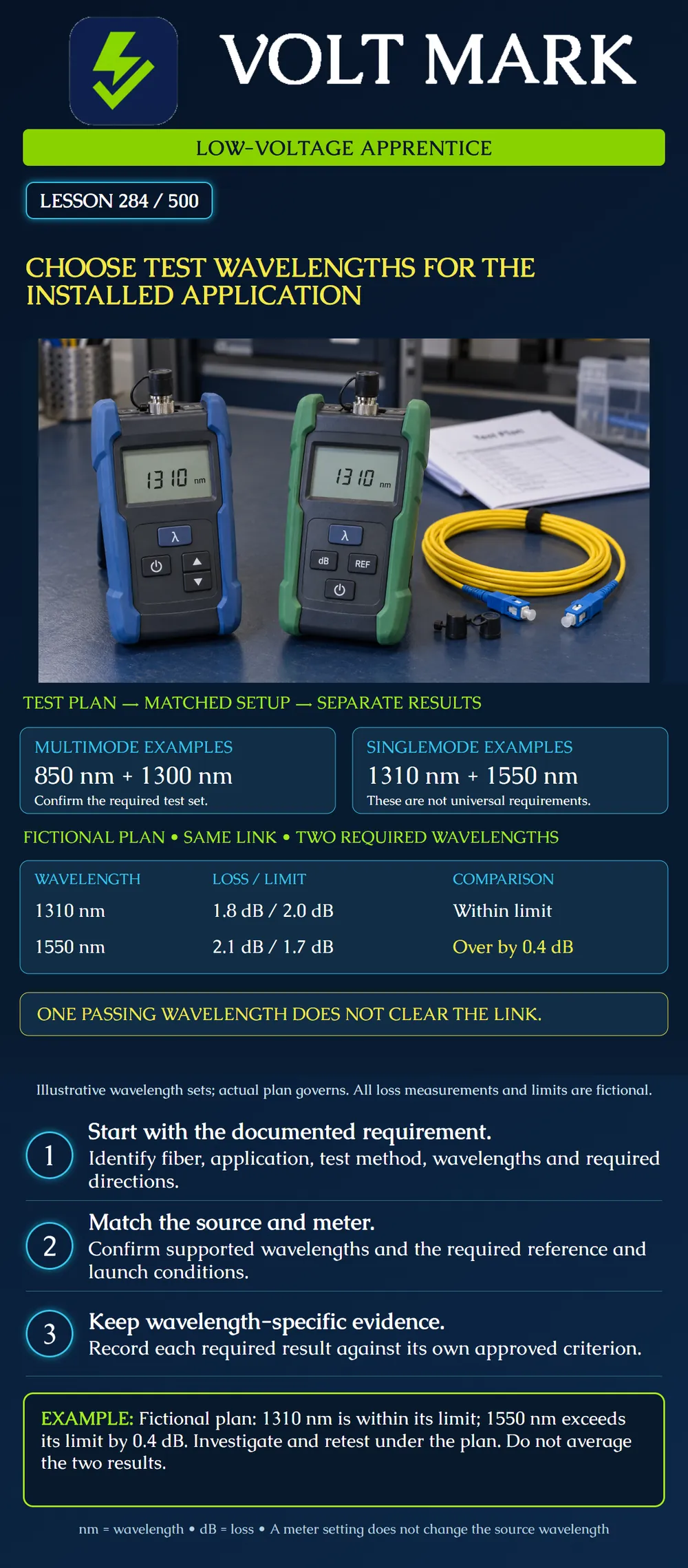
Given a fiber record, an application requirement and an approved test plan, identify the required wavelength set and the evidence needed at each wavelength. Explain why a passing result at one wavelength cannot replace a missing or failing result at another.
Wavelength is expressed here in nanometers, abbreviated nm. Optical loss is expressed in decibels, abbreviated dB. Keep both with the result: “1.8 dB at 1310 nm” identifies a measurement more clearly than “1.8.”
Begin with the documentation. Establish which installed fibers and endpoints are in scope, their verified fiber type, the application to be supported, and the governing acceptance procedure. The test plan should identify wavelengths, test methods, directions, reference procedure and limits. Resolve absent or conflicting requirements with the responsible project authority before testing. Jacket color alone is not sufficient evidence.
Common equipment examples include multimode sources at 850 and 1300 nm, and singlemode sources at 1310 and 1550 nm. The Fluke SimpliFiber Pro datasheet documents these two source configurations. They illustrate available equipment, not a rule requiring these pairs for every installation.
Distinguish the service's operating wavelengths from the acceptance test set. A service description naming one wavelength does not by itself cancel a second wavelength required by the approved cabling acceptance plan. Specialized systems need their own documented requirements; this lesson does not prescribe a test set for every passive optical network or wavelength-division system.
Before a loss test, confirm that the source emits the required wavelength and that the meter supports the measurement and is set or automatically matched correctly under its instructions. A meter setting does not retune an unrelated source. For each wavelength, establish the reference and configuration required by the instrument procedure and plan; automated equipment may manage multiple wavelengths within one test sequence. Match the required fiber, connectors and launch conditions as well. This lesson is not a complete connection or reference-setting procedure.
Record results by link, fiber, wavelength and required direction. Preserve the applicable limit and test configuration with each measurement. Do not move a result from one wavelength into another wavelength's blank field. Do not assume a shared filename means that all required measurements are present.
An approved training plan calls for two measurements on the same link: 1310 nm: measured loss 1.8 dB, maximum allowed 2.0 dB. 1550 nm: measured loss 2.1 dB, maximum allowed 1.7 dB.
The 1310 nm comparison has 2.0 − 1.8 = 0.2 dB of margin. The 1550 nm comparison exceeds its limit by 2.1 − 1.7 = 0.4 dB. The required set is not passing. Neither the average of the two measurements nor the better result overrides the failing comparison. The numerical limits are invented for this exercise and are not national, manufacturer or code limits. Apply any prescribed instrument decision rules and uncertainty treatment on a real project.
The table does not identify the cause of failure. It does not prove a bend, dirty connector, bad splice or wrong reference. Follow the approved troubleshooting process, verify the setup and preserve the original result. Retest as required after an authorized correction, keeping traceable records. Do not simply loosen the limit.
For a supervised training assignment, record:
Mistake: Switching the meter to 1300 nm while leaving an 850 nm-only source connected and recording a 1300 nm result. Correction: Verify the source output and compatible meter configuration for the required wavelength; changing the meter setting does not change the emitted light.
Mistake: Averaging the passing 1310 nm result with the failing 1550 nm result to report one pass. Correction: Compare each required wavelength against its own applicable limit and retain the failing comparison for authorized investigation.
Mistake: Treating one saved file as proof that only one wavelength was tested, or as proof that every wavelength was tested. Correction: Open the record and reconcile its actual fiber, wavelength and direction entries against the plan rather than inferring coverage from file count.
Fluke Networks, SimpliFiber Pro Multimode and Singlemode Sources: https://www.flukenetworks.com/edocs/datasheet-simplifiber-pro-multimode-and-singlemode-sources Read for the documented source wavelength configurations and compatible dual-wavelength recording and automatic detection features. Product-specific behavior is not generalized to all meters. The exercise, worksheet and invented loss limits are original instructional material.
Texas journeyman, 15 questions, scored by topic against the 70% mark. No card, and no account needed to start.
Free study material for low-voltage apprentices. This is a national foundation course: requirements differ by state and by local jurisdiction, and a practice that is common in one place is not a rule everywhere. Nothing here is a licence, a certification, or authority to work unsupervised, and completing it does not count as apprenticeship hours or continuing-education credit. Check the codes adopted where you are working, the licensing authority for that work, and your employer's safety programme. VoltMark is not affiliated with, endorsed by, or sponsored by NFPA, OSHA, NICET, BICSI, FOA, or any state or local licensing authority.

Electrician licensing exam prep: practice questions, timed exam simulations, and step-by-step help finding every answer in the NEC.