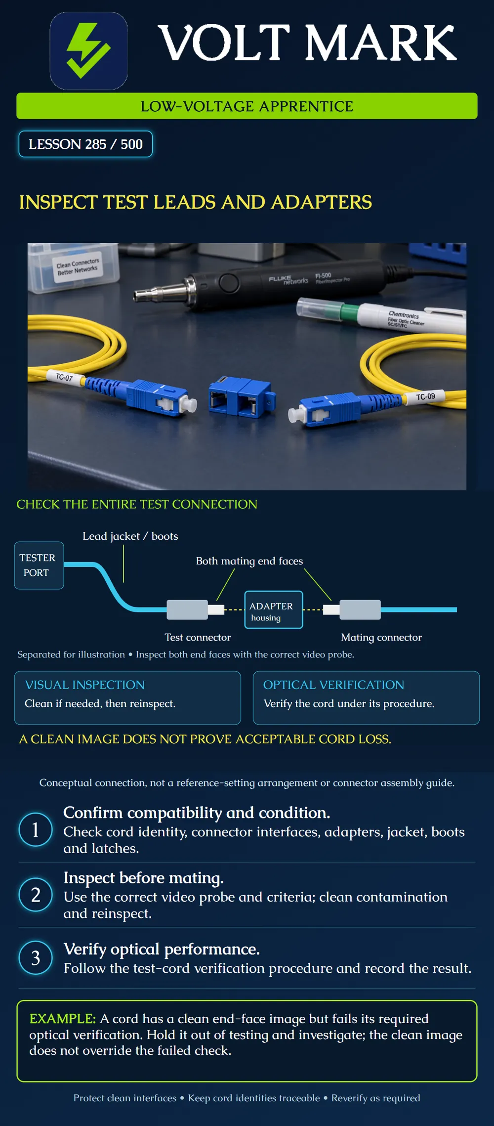
Distinguish compatibility, physical condition, end-face inspection and optical verification when preparing fiber test leads and adapters. Decide what evidence is missing before a test setup can be used.
The test accessories are part of the measurement system. A clean-looking cable is not automatically a suitable test reference cord. Fluke distinguishes reference-grade test cords from ordinary patch cords and describes verification of test cords during use. Select accessories under the actual instrument instructions and test plan. Do not borrow numerical connector limits or verification intervals from a different product or an older article and treat them as universal.
Use an identifiable kit. Record cord and adapter identities, intended instrument, fiber compatibility and connector interfaces. Check the specified polish and mating arrangement; a connector fitting mechanically does not establish optical compatibility. A coupling adapter between two connectors and an interchangeable instrument input adapter have different roles. Use the instructions for the actual accessory rather than assuming the illustrated coupling adapter represents every instrument port.
Examine accessible physical parts before use. Look for jacket cuts, crushing, severe kinks, loose or damaged boots, damaged connector housings or latches, and suspect adapter housings or retention features. Set questionable accessories aside for evaluation. Do not insert sharp tools into an alignment sleeve or improvise an adapter repair. A visual check of an adapter's exterior cannot prove that its internal alignment is satisfactory.
Inspect mating end faces using the correct video probe, tip and inspection criteria. Include the accessible mating interface on the other side, not only the loose test lead. Clean contamination using the approved materials and method, then reinspect. A protective cap is not an inspection result. If inspection identifies damage or a persistent failure, follow the disposition procedure rather than cleaning indefinitely.
End-face inspection and optical cord verification answer different questions. The inspection examines the interface against the selected criteria. Optical verification checks the cord's performance in the specified test arrangement. A passing image does not prove acceptable loss. Use the instrument's prescribed verification process and retain its result. Establish re-verification requirements in the work procedure; contamination, replacement, handling damage or unexplained results warrant attention. Do not continue reporting questionable measurements merely because a reference was set earlier.
The upper diagram separates a test connector, a coupling adapter and a mating connector so the learner can identify them. Dashed gaps are illustrative; they are not instructions to leave an optical connection partly engaged. The cyan curve represents a lead, not a prescribed bend radius. The drawing does not specify a one-, two- or three-cord reference method. Lesson 286 addresses selecting and setting the specified reference.
The two lower panels show separate checks. Complete end-face inspection and the required optical verification. Neither substitutes for the other. The diagram's generic connector shapes intentionally do not prescribe a particular LC, SC or multifiber assembly.
Cord TC-07 has a documented compatible part number, an intact jacket and a passing end-face inspection image. Its required optical verification fails. The learner must hold TC-07 out of testing, preserve the result and investigate under the approved procedure. The evidence does not yet identify whether the issue is the cord, mating interface, adapter, reference or test configuration. Do not label a cause without supporting evidence.
A supervisor substitutes verified compatible cord TC-09. Record the changed cord identity and perform the required setup and reference checks before continuing. Review the affected results under the project procedure; do not silently replace TC-07 in the records or discard the earlier failure.
Prepare paper tags for four fictional accessories: A: correct identification, no observed damage, inspection and verification records complete. B: correct identification, cracked connector latch. C: unlabeled cord with a clean end-face image. D: correct identification and clean image, optical verification missing.
Discuss which evidence supports each disposition. A is a candidate for use only within the documented setup and validity conditions. B needs removal from the working kit for evaluation. C needs identity and compatibility resolved. D needs the required verification. None of these paper cases authorizes live network connections.
Record accessory identity, manufacturer part number, supported setup, observed condition, inspection method and criteria, inspection outcome, any cleaning and reinspection, verification procedure and result, date, operator and disposition. Link the record to the test session. If a kit contains six required cords and five have complete records, one remains unresolved. Counting five records cannot certify the sixth cord.
Use isolated training equipment and the site's optical-safety procedure. Never look into a fiber or connector to check for light. Confirm appropriate isolation before inspection or connecting a test source. This lesson is an instructional overview, not a complete instrument setup or live-system work procedure.
Mistake: Returning TC-07 to the test kit because its end-face image passes even though optical verification failed. Correction: Keep the cord out of accepted testing, preserve both results and investigate the specified verification arrangement; a clean image does not resolve the optical failure.
Mistake: Replacing a suspect test cord while leaving the original cord identity in the session record. Correction: Record the replacement identity and complete the required verification and reference checks before continuing, then review measurements affected by the earlier uncertainty.
Mistake: Substituting an ordinary patch cord because its connectors fit the same adapters. Correction: Verify the cord's documented suitability for the specified reference setup and complete its required checks rather than inferring reference-grade performance from physical fit.
Fluke Networks, Test reference cords (TRCs) vs. patch cords, dated October 16, 2014: https://www.flukenetworks.com/knowledge-base/certifiber-pro/test-reference-cords-trcs-vs-patch-cords Used for the distinction between reference cords and patch cords and the need to verify test cords. Historical numeric limits, suggested counts and field-fabrication advice are not adopted here.
Fluke Networks, New Solutions for VSFF Applications, August 12, 2025: https://www.flukenetworks.com/blog/cabling-chronicles/vsff-test-inspect-clean Used for inspection of mating end faces, conditional cleaning, appropriate tools and product-supported verification. Specific product features do not apply automatically to every tester.
Texas journeyman, 15 questions, scored by topic against the 70% mark. No card, and no account needed to start.
Free study material for low-voltage apprentices. This is a national foundation course: requirements differ by state and by local jurisdiction, and a practice that is common in one place is not a rule everywhere. Nothing here is a licence, a certification, or authority to work unsupervised, and completing it does not count as apprenticeship hours or continuing-education credit. Check the codes adopted where you are working, the licensing authority for that work, and your employer's safety programme. VoltMark is not affiliated with, endorsed by, or sponsored by NFPA, OSHA, NICET, BICSI, FOA, or any state or local licensing authority.

Electrician licensing exam prep: practice questions, timed exam simulations, and step-by-step help finding every answer in the NEC.