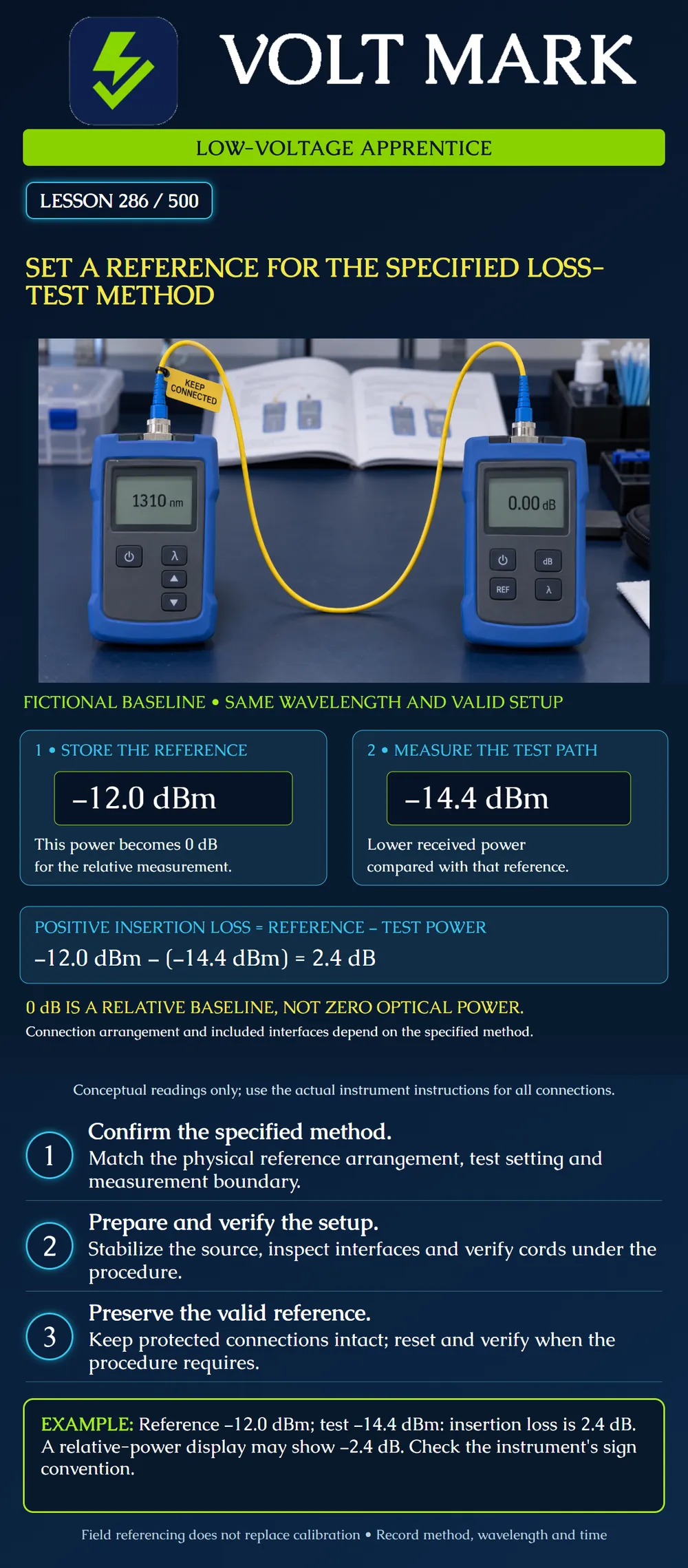
Explain what a loss-test reference represents, identify the documented setup needed to establish it, and recognize changes that require the reference to be repeated. Calculate positive insertion loss from two compatible power readings.
A field reference establishes the baseline used for a relative loss measurement. It does not replace the instrument's required calibration. The stored reference must correspond to the specified method, wavelength and actual test configuration. Selecting a method in software does not physically create that arrangement.
Confirm the approved plan and current instrument procedure. Identify the link endpoints, interfaces included in the measurement, required wavelengths and directions, reference method, accessories and applicable limits. The physical connections and the selected method must agree. If they do not, resolve the mismatch before accepting results.
Fluke's guidance recommends the one-jumper reference when feasible for link testing because it includes the end connections in the measured link loss. Other methods change what is referenced out and require their own arrangements and interpretation. Do not substitute a two- or three-jumper method merely because the cords happen to be available. Obtain the documented method applicable to the actual interfaces and acceptance boundary.
Prepare the instrument and reference accessories. Allow stabilization as specified by the manufacturer rather than assuming a universal warm-up duration. Inspect the interfaces, clean only when needed and reinspect. Confirm compatible cords, adapters and launch conditions. Follow the prescribed sequence for setting the reference and verifying the test reference cords; this lesson does not replace the connection diagram or the instrument's instructions.
Preserve the connections that maintain the reference. In the Fluke workflow cited below, removing a test reference cord from an output port invalidates the reference, requiring it to be set again. The procedure distinguishes output connections from input connections that are deliberately moved. Identify the correct ports; do not interpret this as permission to move any connector freely.
Record the reference method, wavelengths, instrument and accessory identities, reference values, time and cord verification evidence. Recheck validity under the procedure after configuration changes, interruptions or suspect results. Retain a traceable record of a reset. Review potentially affected measurements instead of assuming a new reference retroactively validates earlier tests.
Before touching the training setup, identify the procedure revision, instrument ports, required cords, interfaces being included, wavelength set and source stabilization requirement. Ask the supervisor to confirm the proposed arrangement against the actual instrument diagram. Record inspection and verification outcomes, reference values and time. Mark which connections must remain intact and what events require a reset. Use isolated training equipment and applicable optical-safety procedures; do not connect to an active service or look into an optical interface.
Mistake: Recording the absolute reference power as 0 dBm because the relative display reads 0 dB. Correction: Keep the quantities separate and retrieve the actual stored absolute reference when required; the example retains -12.0 dBm while defining relative zero.
Mistake: Selecting one-jumper reference in software while physically referencing through a different cord arrangement. Correction: Compare every connection with the applicable instrument diagram and acceptance boundary, then establish the reference using the documented arrangement.
Mistake: Resetting the reference after an output-cord disconnection and assuming earlier suspect results are now valid. Correction: Record when validity was lost and restored, identify affected measurements and review or retest them under the approved procedure; the later reference cannot repair earlier evidence.
Fluke Networks, Why the 1-jumper reference is recommended for accurate fiber optic testing, February 24, 2026: https://www.flukenetworks.com/blog/cabling-chronicles/why-1-jumper-reference-recommended Used for method-dependent boundaries and the manufacturer's connection-preservation and verification workflow. Its informal use of “calibrate” for field referencing is not used as a substitute for actual instrument calibration. Numeric accessory limits and fixed test counts are not prescribed here.
Fiber Optic Association, Fiber Optic Measurement Units: dB and dBm: https://www.thefoa.org/tech/ref/testing/test/dB.html Used for absolute versus relative units and sign conventions. The poster values and practice cases are original. No generic safety assurances or typical component loss limits from that page are adopted.
Texas journeyman, 15 questions, scored by topic against the 70% mark. No card, and no account needed to start.
Free study material for low-voltage apprentices. This is a national foundation course: requirements differ by state and by local jurisdiction, and a practice that is common in one place is not a rule everywhere. Nothing here is a licence, a certification, or authority to work unsupervised, and completing it does not count as apprenticeship hours or continuing-education credit. Check the codes adopted where you are working, the licensing authority for that work, and your employer's safety programme. VoltMark is not affiliated with, endorsed by, or sponsored by NFPA, OSHA, NICET, BICSI, FOA, or any state or local licensing authority.

Electrician licensing exam prep: practice questions, timed exam simulations, and step-by-step help finding every answer in the NEC.