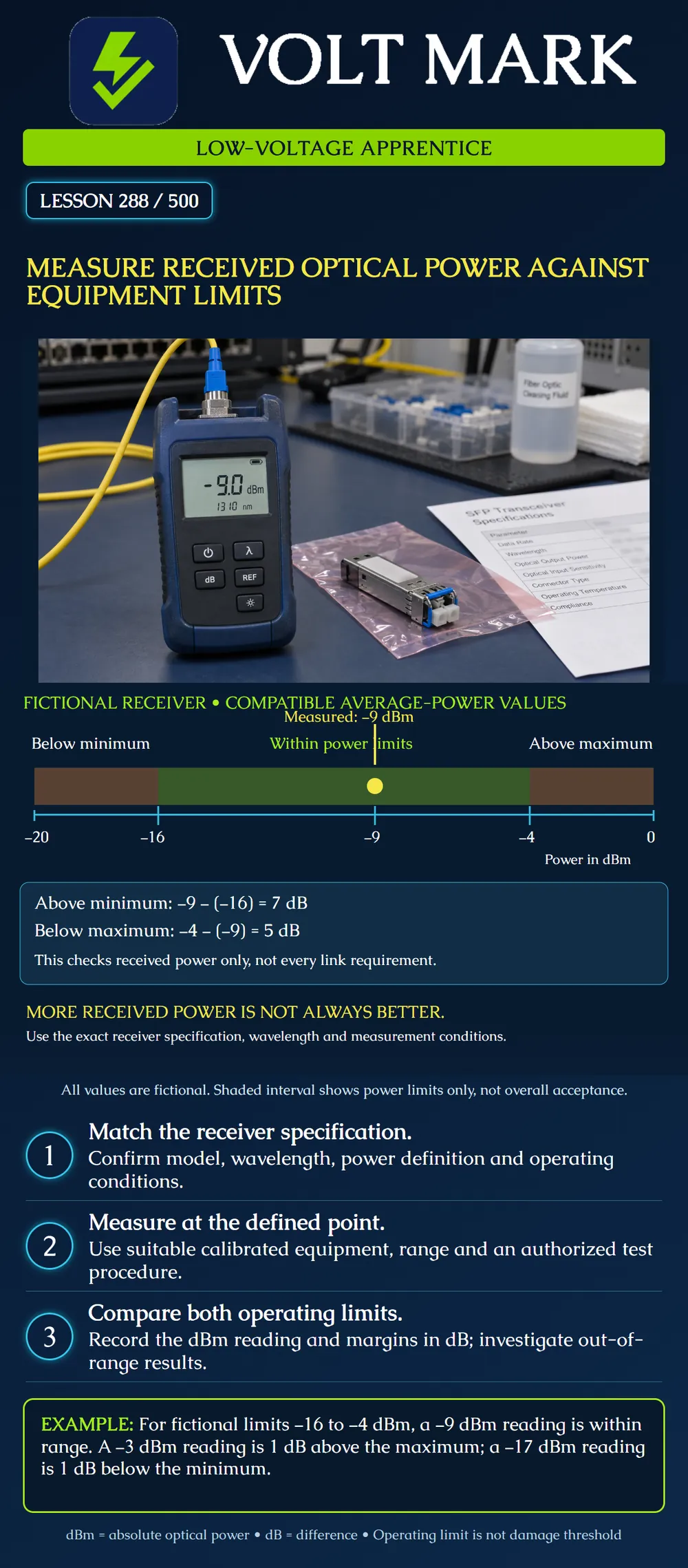
Compare a valid received optical-power measurement with compatible minimum and maximum receiver operating limits. Distinguish absolute power, power margin, loss, optical modulation amplitude and damage threshold.
Received optical power is a power level at a defined measurement point. It may be reported in dBm, meaning decibels relative to one milliwatt. Insertion loss is a difference between power levels and is reported in dB. A single received-power reading is not, by itself, a measurement of the cable's insertion loss.
Identify the exact receiver and the documentation for its operating mode. Check wavelength, data rate, relevant environmental conditions and the definition of the power specification. Cisco's transceiver tables illustrate why this matters: specifications vary by module, and some distinguish average power from optical modulation amplitude, abbreviated OMA. An average-power measurement cannot simply be compared with an OMA-only criterion as though they were interchangeable.
Read both ends of the permitted operating range. A receiver needs sufficient power for the specified performance, but excessive input can exceed its operating limit. An overload or maximum operating specification is not the same as a damage threshold. Do not use a damage threshold as the normal operating target. Even power within the permitted interval does not prove that all other optical and application requirements are satisfied.
Plan the measurement point. A meter attached to the receiver-end fiber under an approved procedure measures power at that interface; it does not automatically account for a different point or additional accessories. If a monitor tap is used, apply only the documented method and applicable tap correction. Do not invent a correction to obtain a passing value. Identify whether a record came from an external meter or the module's internal diagnostics.
Select measurement equipment suitable for the wavelength, signal and expected input range. Confirm calibration status and the meter's own maximum input restrictions. Use absolute-power mode and the correct wavelength setting according to the instrument instructions. Wavelength selection on a general power meter is not proof that it has separated multiple optical channels; specialized signals require an appropriate measurement procedure and instrument.
Measurement may interrupt service if the receiver connection is removed. Follow the authorized work plan and optical-safety procedure. Isolate sources for connector inspection and handling as required, and energize only the defined measurement arrangement under supervision. Never look into a fiber or port. This lesson does not authorize disconnecting a live campus service or connecting unknown optical power to a meter.
Assume that the instrument, measurement point, wavelength and average-power definitions all match the fictional receiver specification. Minimum operating input: −16 dBm. Maximum operating input: −4 dBm. Measured input: −9 dBm.
Above the minimum: −9 − (−16) = 7 dB. Below the maximum: −4 − (−9) = 5 dB.
The reading is inside the stated power interval. These margins are arithmetic distances from the specified boundaries, not permission to ignore measurement uncertainty, required design reserve or other system requirements. The displayed interval is evenly spaced in dBm; it is not a linear scale of optical watts.
Two further cases: At −3 dBm, received power exceeds the maximum by −3 − (−4) = 1 dB. At −17 dBm, received power falls below the minimum by −16 − (−17) = 1 dB. The first case has too much power and the second too little. More negative dBm means less power. These fictional limits are not specifications for a real product.
Record project, endpoint, fiber, receiver model and operating mode, specification revision, wavelength, power definition, measurement point, instrument identity, calibration status, reading, applicable minimum and maximum, decision rule, time and operator. Preserve out-of-range results and any subsequent authorized correction and retest.
What unit represents the absolute reading here? dBm. What unit represents the distance from an operating limit? dB. Is −3 dBm stronger or weaker than −9 dBm? Stronger. What is the poster's distance above minimum? 7 dB, calculated as -9 minus (-16). What is its distance below maximum? 5 dB, calculated as -4 minus (-9). Does an in-range power reading establish complete application performance? No. It answers the stated power comparison while other application requirements remain separate. Can a damage threshold replace an operating maximum? No. Damage and correct operating performance are different limits.
Use the fictional average-power interval of -16 to -4 dBm. Assume compatible definitions, measurement points and valid readings. Classify -12 dBm, -2 dBm and -18 dBm; calculate each reading's distances from the applicable boundaries. Then explain what changes if the only available minimum specification is expressed in OMA. Answer guide: -12 dBm is inside the interval, 4 dB above minimum and 8 dB below maximum. -2 dBm exceeds the operating maximum by 2 dB. -18 dBm is below the minimum by 2 dB. None is a cable-loss measurement by itself. With an OMA-only minimum, stop the average-power comparison and obtain compatible specifications or the required measurement method; do not compare the numbers directly.
Mistake: Using a receiver's damage threshold as its acceptable operating maximum. Correction: Locate the applicable operating limit for the exact mode and compare against that boundary; being below a damage threshold does not establish valid operation.
Mistake: Comparing an average-power meter reading directly with an OMA-only sensitivity specification. Correction: Identify the power definition on both records and obtain compatible evidence before making the acceptance comparison.
Mistake: Averaging internal diagnostics and an external-meter reading to hide disagreement. Correction: Record each method and measurement point separately, check the relevant specifications and investigate the discrepancy before assigning a disposition.
Cisco, 10GBASE SFP+ Modules Data Sheet, updated July 1, 2026: https://www.cisco.com/c/en/us/products/collateral/interfaces-modules/transceiver-modules/data_sheet_c78-455693.html Tables 4–6 and their notes support distinctions among module-specific receive limits, average power, OMA, overload and damage thresholds. No real product's numerical limits are reproduced as the training example.
Fluke Networks, Monitoring Optical Power – DTX xFM Series: https://www.flukenetworks.com/knowledge-base/dtx-efm2-fiber-adapters/monitoring-optical-power-dtx-xfm-series Used for the distinction of power-monitoring mode and wavelength selection. Its model-specific controls are not prescribed for other instruments.
Texas journeyman, 15 questions, scored by topic against the 70% mark. No card, and no account needed to start.
Free study material for low-voltage apprentices. This is a national foundation course: requirements differ by state and by local jurisdiction, and a practice that is common in one place is not a rule everywhere. Nothing here is a licence, a certification, or authority to work unsupervised, and completing it does not count as apprenticeship hours or continuing-education credit. Check the codes adopted where you are working, the licensing authority for that work, and your employer's safety programme. VoltMark is not affiliated with, endorsed by, or sponsored by NFPA, OSHA, NICET, BICSI, FOA, or any state or local licensing authority.

Electrician licensing exam prep: practice questions, timed exam simulations, and step-by-step help finding every answer in the NEC.