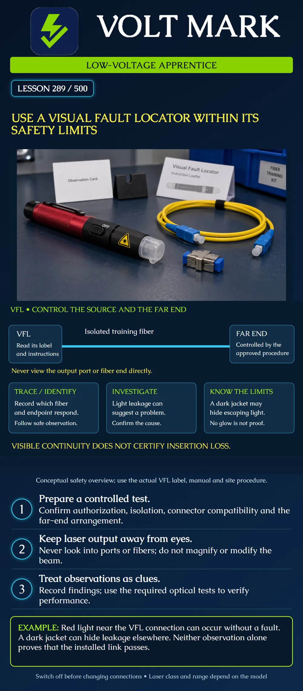
Explain the purpose and limits of a visual fault locator, prepare a supervised isolated-fiber demonstration, and distinguish an observation from a verified fault or acceptance result.
A visual fault locator, abbreviated VFL, injects visible light into a fiber. It can assist fiber identification, continuity checks and investigation of some accessible faults. It is not an insertion-loss certification result. Seeing light does not establish a dB loss value or prove that the link meets the requirements of its operating application.
Read the label and instructions for the actual instrument. Laser classification, output, adapters and range depend on the model. Do not assume that every pen-shaped VFL has the same safety characteristics. Do not substitute a more powerful device to overcome a difficult viewing condition without the approved equipment and procedure.
Never look directly into the VFL output or an illuminated fiber end. Do not magnify or modify the laser output. An ordinary magnifier or direct-view microscope is not a safe way to find a weak signal. Control the far end and any other exposed outputs so that other workers are not exposed unexpectedly. Coordinate with the supervisor and anyone working at the other endpoint.
Before the exercise, identify the training fiber and confirm that it is isolated from operating equipment and other optical sources under the site procedure. Switch off the VFL before connecting, disconnecting or changing adapters. Inspect and clean interfaces using the appropriate procedure with sources controlled. Use compatible connectors and adapters without forcing the connection.
Arrange the observation method specified by the actual manufacturer and site procedure. Keep eyes out of the output path. Fluke's OptiFiber/CertiFiber guidance describes observing connector output on white paper rather than looking into the end. This is product guidance, not blanket permission to use any surface with any laser class or output. Have the supervisor establish the suitable arrangement for the actual device before energizing it.
Activate only the required mode under the instructions. Observe without touching or deliberately stressing the fiber. Turn the VFL off before changing the setup, inspecting an end face or making an authorized correction. Protect the interfaces and leave the equipment in the prescribed safe state when finished.
Light leaking at an accessible location can suggest a bend, damaged fiber, connection issue or splice issue. It is a clue for investigation, not a complete diagnosis. Fluke also notes that light near the source connection can be visible even without a fault. Dark jackets can prevent leakage from being seen. Therefore, both “I see a glow” and “I see no glow” require context.
Do not bend a working cable sharply to create a visible demonstration. Use a purpose-built training sample or a diagram. Do not open, adjust or reseat a splice while the source remains on merely to watch the glow change.
Visible continuity does not replace the approved loss, length, polarity or other required acceptance tests. Range is also a limitation. An advertised VFL range is not a guarantee for every installed path, and a missing visible response is not proof that the fiber is broken. Confirm the setup, identity, instrument condition and applicable limitations before drawing a conclusion.
The line between the source and controlled far end is conceptual. It does not depict an exposed free-space beam. The three panels separate identification, investigation and limitations. The poster deliberately avoids a numerical laser power, class or distance because those must come from the actual device documentation.
Record the instrument model, label classification, instruction revision, approved mode, training fiber identity, isolation confirmation, endpoint control, observation arrangement and observed outcome. State separately what the observation suggests and what remains unverified. List the next required measurement. Do not convert a visual impression into an invented loss number.
Mistake: Recording a loss pass because visible light reached the expected far end. Correction: Record the observed continuity and endpoint identity, then obtain the separate loss and other acceptance measurements required by the plan.
Mistake: Condemning a connector solely because a glow appears beside the VFL output. Correction: Turn the source off and investigate under the actual device procedure; source-adjacent glow can occur without a fault, so preserve the observation without inventing a diagnosis.
Mistake: Using a magnifier to find a faint response on a long route. Correction: Stop that viewing approach, confirm the device limitations and approved indirect observation arrangement, and use suitable test equipment when the VFL cannot resolve the question.
Fluke Networks, VFL – Visual Fault Locator, OptiFiber Pro guidance: https://www.flukenetworks.com/knowledge-base/optifiber-pro/vfl-visual-fault-locator Reference for uses, indirect observation, source-adjacent glow and dark-jacket limitations. Splice adjustment advice is not adopted as an energized-work instruction.
Fluke Networks, VisiFault product page: https://www.flukenetworks.com/datacom-cabling/fiber-testing/VisiFault-Visual-Fault-Locator Reference for product-specific functions and specifications. No universal classification or range is inferred.
Fluke Networks, VisiFault Instruction Sheet, Rev. 2: https://www.flukenetworks.com/findit/9820324 Manufacturer download landing page opened. The PDF download returned an access error. Search-indexed manufacturer instruction-sheet excerpts explicitly prohibit direct viewing and magnifying or modifying output; full PDF text was not retrieved. The actual device manual must be consulted before field use. No claim of full manual review is made.
Texas journeyman, 15 questions, scored by topic against the 70% mark. No card, and no account needed to start.
Free study material for low-voltage apprentices. This is a national foundation course: requirements differ by state and by local jurisdiction, and a practice that is common in one place is not a rule everywhere. Nothing here is a licence, a certification, or authority to work unsupervised, and completing it does not count as apprenticeship hours or continuing-education credit. Check the codes adopted where you are working, the licensing authority for that work, and your employer's safety programme. VoltMark is not affiliated with, endorsed by, or sponsored by NFPA, OSHA, NICET, BICSI, FOA, or any state or local licensing authority.

Electrician licensing exam prep: practice questions, timed exam simulations, and step-by-step help finding every answer in the NEC.