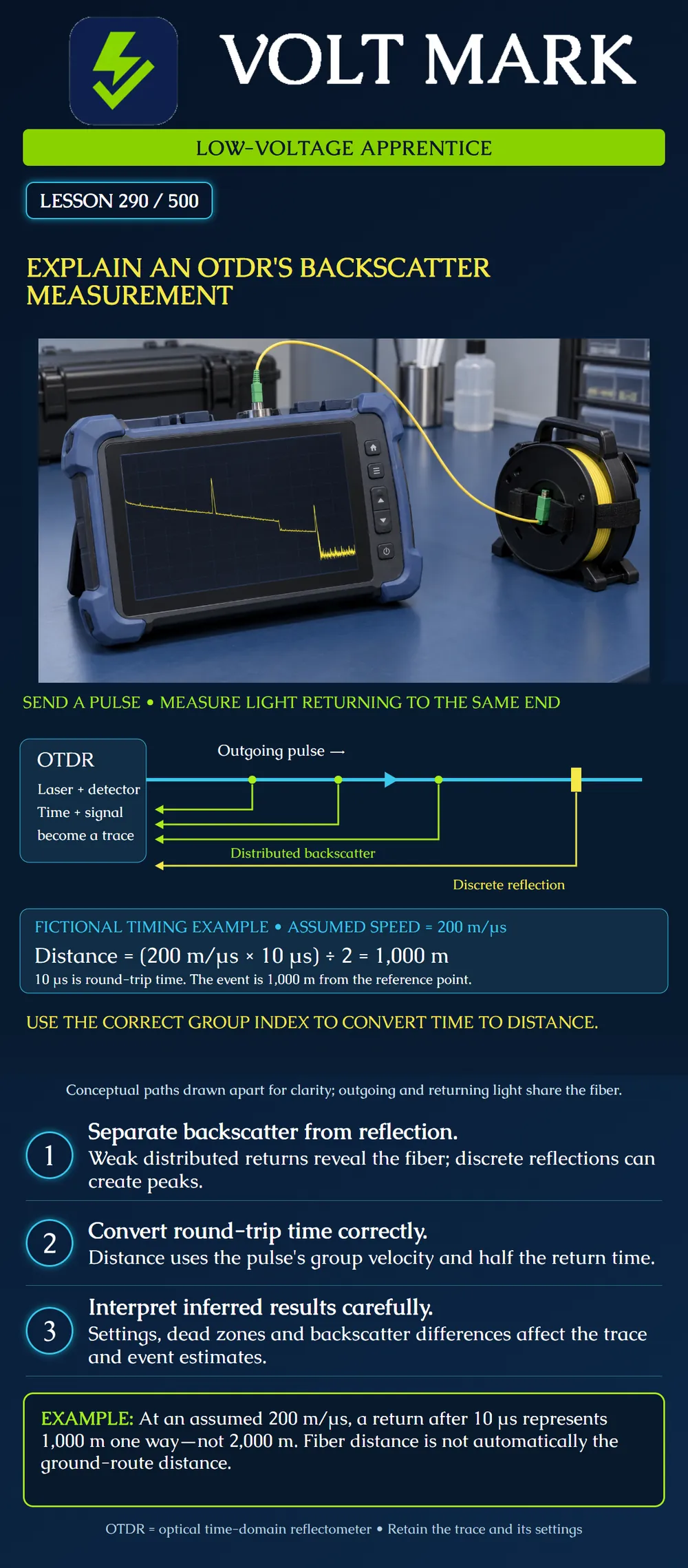
Explain how an optical time-domain reflectometer obtains information from returning light. Distinguish distributed backscatter from discrete reflection, calculate a simple one-way distance from round-trip time, and recognize limits of the inferred result.
An optical time-domain reflectometer, or OTDR, sends short optical pulses into a fiber and measures light returning to the same instrument. Processing these signals produces a trace and event estimates. Unlike an OLTS measurement with a power meter at the far end, this is an indirect measurement based on returned light.
A small portion of light is scattered back along the fiber. This distributed Rayleigh backscatter provides information about the fiber along its length. A discrete change in optical interface can also produce a stronger Fresnel reflection, which may appear as a peak. Not every loss event creates a prominent reflective peak, so the absence of a peak does not prove the absence of loss.
The instrument uses timing to assign distance. The relevant propagation speed is the pulse's group velocity in the fiber, determined through the appropriate group-index setting. The travel time includes the outward trip and the return trip. For a simple uniform-fiber example: One-way distance = group velocity × round-trip time ÷ 2. Equivalently, distance = c × time ÷ (2 × group index), where c is the speed of light in vacuum.
Use the appropriate fiber data and wavelength-dependent instrument setup rather than adjusting the index until a trace fits a desired route length. Optical distance follows the fiber. Cable construction, slack, launch fiber and the chosen reference point affect its relationship to a drawing or ground route. Do not order excavation from a screen distance alone.
Backscatter levels are used to infer attenuation and event loss. Those results require suitable settings and interpretation. A strong reflection can temporarily prevent the detector from resolving nearby features, producing a dead zone. Pulse width, range, averaging and the available signal influence what can be distinguished. Lesson 291 develops those settings.
Differences in backscatter properties across a joint can bias a one-direction event-loss estimate. An apparent gain does not mean a passive splice generated optical power. Use the required bidirectional evaluation and the approved analysis method where applicable. Do not treat a single automatic event-table entry as a complete diagnosis.
The cyan arrow is an outgoing pulse. The lime arrows represent distributed returns from different positions. The yellow path represents one discrete reflection. All travel within the same fiber; the drawing separates them vertically only to make direction visible. The yellow mark is a conceptual reflective interface, not a prescribed connector or a confirmed defect.
The illustration is not an actual trace, does not show relative signal amplitudes, and does not prescribe launch or receive cable arrangements. Those arrangements must follow the instrument instructions and test plan. A drawing of several return paths should not be read as several physical fibers.
Assume a uniform training fiber with a group velocity of exactly 200 meters per microsecond for the arithmetic exercise. A return from a defined event arrives 10 microseconds after launch, measured from the exercise's reference point. Round-trip travel distance = 200 × 10 = 2,000 meters. One-way event distance = 2,000 ÷ 2 = 1,000 meters.
The assumed speed is simplified. It is not a recommended universal instrument setting. Real distance accuracy depends on the correct fiber parameters and measurement conditions. No loss value or acceptance limit can be obtained from these timing numbers alone.
Use saved training traces or an isolated training fiber under the site's optical-safety procedure. Do not look into optical interfaces or connect the instrument to an active service without the specific authorized equipment and procedure. Mark the trace identity, direction, wavelength, group-index setting, pulse width, range, averaging, reference point and launch/receive arrangement. Distinguish observations from conclusions needing further evidence.
Where is the returned light detected? At the OTDR end. What provides a distributed signal along the fiber? Rayleigh backscatter. Does every loss event require a reflective peak? No. Loss may occur without a prominent discrete reflection; examine the trace with suitable settings. Why divide elapsed time by two? It includes outward and return travel. What is the one-way distance in the main example? 1,000 meters, from 200 times 10 divided by two. Does optical distance automatically equal ground-route distance? No. Fiber length includes effects such as slack and launch fiber that must be reconciled to the field reference. Does a one-direction apparent gain prove an active amplifier? No. Backscatter differences can bias a passive joint's event estimate; evaluate the required opposite-direction evidence.
Mistake: Reporting 2,000 meters as the one-way event distance from the exercise's 10-microsecond return. Correction: Account for both outward and return travel: 200 meters per microsecond times 10 microseconds divided by two gives 1,000 meters one way.
Mistake: Treating the unresolved region after a strong peak as proof that no nearby event exists. Correction: Record the resolution limitation and evaluate the applicable dead zone and acquisition settings before making an event conclusion.
Mistake: Changing the group-index setting until the displayed distance matches a ground-route drawing. Correction: Use the appropriate fiber data and wavelength setup, then reconcile optical distance with launch fiber, slack and the actual cable route instead of forcing agreement.
EXFO, Optical Time-Domain Reflectometer glossary: https://www.exfo.com/en/resources/glossary/optical-time-domain-reflectometer-otdr/ Reference for pulse/return operation, signal processing, Rayleigh backscatter, discrete reflections and dead-zone limitations. Broad marketing statements about complete event information are not treated as guaranteed detection.
Fiber Optic Association, Fiber U Quickstart Guide: Fiber Optic Testing With OTDRs: https://www.thefoa.org/tech/ref/quickstart/OTDR.html Reference for setup, trace interpretation, fiber-distance limitations and documentation. No universal fiber-excess percentage or numerical acceptance threshold adopted. The timing exercise and diagram are original.
Texas journeyman, 15 questions, scored by topic against the 70% mark. No card, and no account needed to start.
Free study material for low-voltage apprentices. This is a national foundation course: requirements differ by state and by local jurisdiction, and a practice that is common in one place is not a rule everywhere. Nothing here is a licence, a certification, or authority to work unsupervised, and completing it does not count as apprenticeship hours or continuing-education credit. Check the codes adopted where you are working, the licensing authority for that work, and your employer's safety programme. VoltMark is not affiliated with, endorsed by, or sponsored by NFPA, OSHA, NICET, BICSI, FOA, or any state or local licensing authority.

Electrician licensing exam prep: practice questions, timed exam simulations, and step-by-step help finding every answer in the NEC.