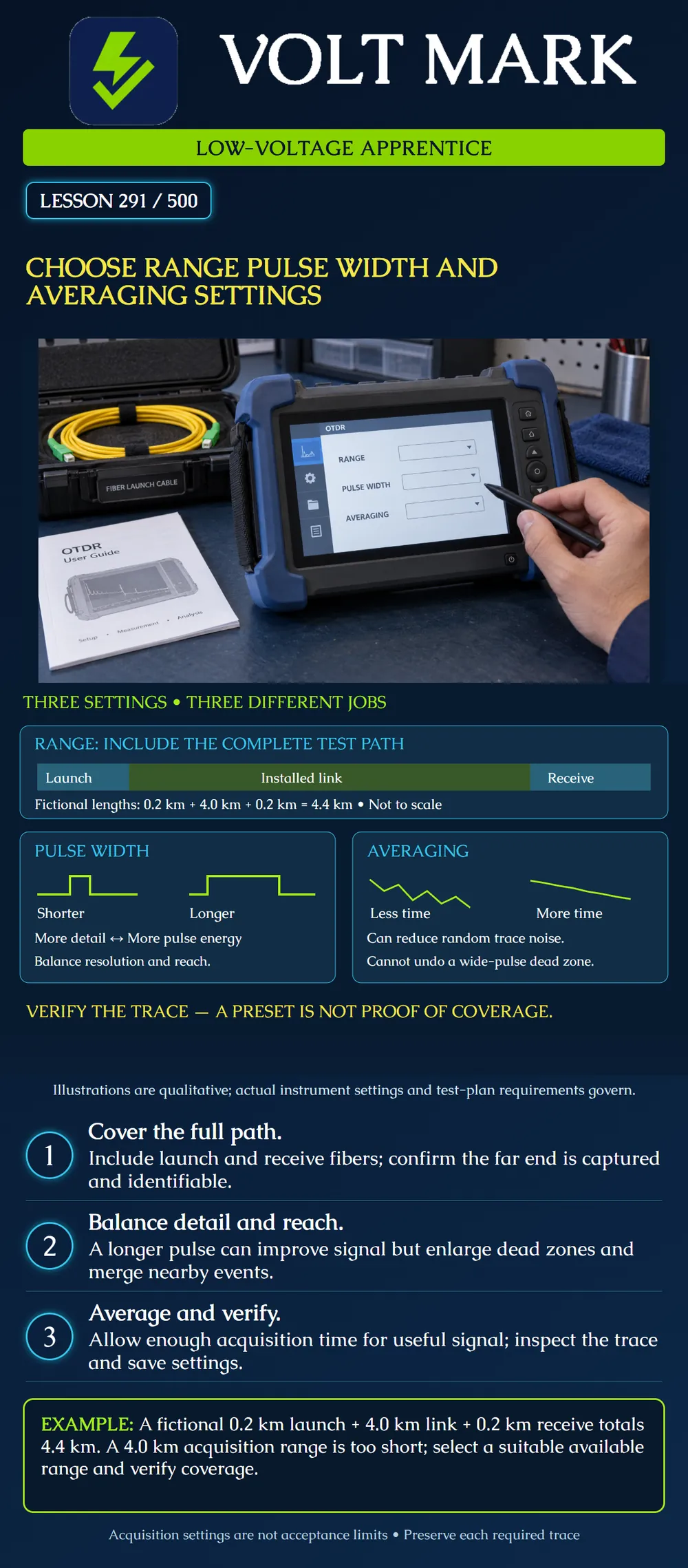
Explain the different purposes of OTDR range, pulse width and averaging. Choose a reasoned starting configuration under the actual test procedure, then verify that the acquired trace supports the required measurements.
Range, pulse width and averaging interact, but they do different jobs. Range defines the acquisition distance window. Pulse width influences pulse energy and the ability to distinguish nearby features. Averaging combines acquisitions to reduce random noise. A useful setting must suit the actual path and measurement objective; no single preset covers every campus, industrial or short premises link.
For a complete-path acquisition, account for the launch fiber, installed link and receive fiber. Select an available range that captures the required path and permits its far end to be identified under the manufacturer's procedure. A large range setting alone does not provide enough optical signal to reach the end. Confirm the trace instead of assuming that a displayed distance scale proves coverage.
A shorter pulse can preserve more detail around closely spaced events, but carries less energy at comparable pulse power. A longer pulse can improve the returned signal and usable reach while increasing dead zones and merging nearby features. Use the shortest pulse that supports the required measurements with adequate signal under the procedure. Some work requires complementary acquisitions or an approved automatic multi-pulse method.
Longer averaging can improve signal-to-noise performance. It takes more time and cannot repair contamination, correct an erroneous group index, extend a truncated acquisition window, or recover spatial detail hidden by an overly wide pulse. Do not confuse a smoother trace with a fully resolved trace.
Start from the documented instrument procedure or approved automatic mode, confirm the settings actually used, and inspect the result. Look for the expected endpoints, useful backscatter around events, excessive noise and unresolved regions. Change the relevant setting deliberately and retain trace identity and settings. Do not weaken acceptance limits or suppress event reporting merely to make a display look clean.
Launch fiber: 0.2 km. Installed link: 4.0 km. Receive fiber: 0.2 km. Total path to the end of the receive fiber: 0.2 + 4.0 + 0.2 = 4.4 km.
A 4.0 km acquisition range cannot capture that whole path. Choose a suitable available range under the instrument instructions and verify the actual endpoint. The exercise does not prescribe a particular menu choice, fixed range multiplier, pulse duration or averaging time.
The two 0.2 km accessory lengths are exercise inputs. They are not universal launch/receive recommendations. Their suitability also depends on the measurement conditions, including pulse width and dead-zone behavior. Lesson 292 addresses launch and receive fibers in more detail.
The top strip shows the three consecutive path segments; its widths are not proportional to the fictional lengths. The pulse drawings show duration differences, not real instrument waveforms. The averaging sketches are qualitative views of noisy and smoother declining signals, not measured traces or acceptance evidence. No event loss or pass/fail threshold can be read from them.
Use an existing training dataset or isolated supervised training setup. Hold fiber identity, direction and wavelength constant while comparing the intended setting change. Record what became clearer and what became less distinguishable. Retain all traces required by the plan. Follow optical-safety and connection procedures; do not connect to a live service without the specifically authorized equipment and method.
For each acquisition, capture fiber ID, direction, wavelength, group-index setting, range, pulse width, averaging or acquisition time, launch/receive arrangement, instrument identity and time. Note whether the far end is visible and whether each required event can be evaluated. Explain why another acquisition is needed when one trace cannot answer all questions.
What is the fictional total path? 4.4 km. Is a 4.0 km range sufficient for it? No. The 4.4 km total includes the launch and receive fibers beyond the installed link. Does longer pulse width generally help or hurt separation of nearby events? It can hurt by increasing dead zones. What does averaging chiefly improve here? Random-noise performance. Can averaging restore detail lost to a wide-pulse dead zone? No. Averaging reduces random noise but does not restore the missing spatial resolution. Is a reporting threshold an acceptance criterion by default? No. It controls event reporting; contractual acceptance criteria must be identified separately.
Mistake: Selecting a 4.0 km range because the installed cable is 4.0 km, ignoring launch and receive fibers. Correction: Include the accessory lengths in the acquisition path, then choose a suitable available range and confirm the far endpoint; this exercise totals 4.4 km.
Mistake: Extending averaging to separate two events that merged after selecting a wider pulse. Correction: Recognize the resolution tradeoff and obtain a suitable shorter-pulse or complementary acquisition under the procedure; smoothing alone does not undo a wide-pulse dead zone.
Mistake: Raising the event-reporting threshold to remove troublesome entries and calling the link acceptable. Correction: Preserve the trace and investigate signal quality and reporting settings, then evaluate the required events against the separate approved acceptance criteria.
EXFO, Optical Time-Domain Reflectometer glossary: https://www.exfo.com/en/resources/glossary/optical-time-domain-reflectometer-otdr/ Reference for dead zones, pulse width, dynamic range and the dependence of specifications on test conditions. No example specification is adopted as a universal setting.
Fluke Networks, Setting the Manual OTDR Mode – DTX Compact OTDR Module: https://www.flukenetworks.com/knowledge-base/dtx-compact-otdr/setting-manual-otdr-mode-dtx-compact-otdr-module Reference for range selection, averaging effects, actual-setting review and detection-threshold limitations. Historical menu steps and fixed times are not prescribed for other instruments.
Texas journeyman, 15 questions, scored by topic against the 70% mark. No card, and no account needed to start.
Free study material for low-voltage apprentices. This is a national foundation course: requirements differ by state and by local jurisdiction, and a practice that is common in one place is not a rule everywhere. Nothing here is a licence, a certification, or authority to work unsupervised, and completing it does not count as apprenticeship hours or continuing-education credit. Check the codes adopted where you are working, the licensing authority for that work, and your employer's safety programme. VoltMark is not affiliated with, endorsed by, or sponsored by NFPA, OSHA, NICET, BICSI, FOA, or any state or local licensing authority.

Electrician licensing exam prep: practice questions, timed exam simulations, and step-by-step help finding every answer in the NEC.