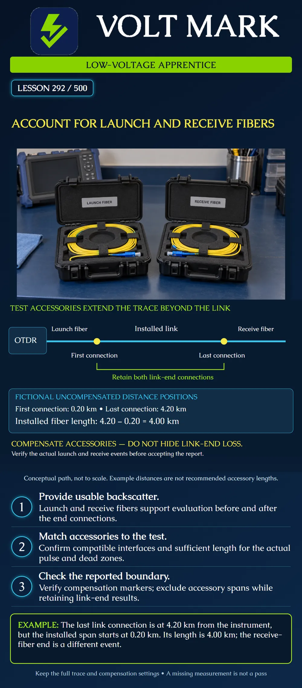
Identify the launch fiber, installed link and receive fiber in an OTDR setup. Explain their roles in end-connection evaluation and verify that reporting boundaries exclude accessories without concealing required link-end results.
A launch fiber is placed between the OTDR and the installed link. A receive fiber, also called a tail fiber, is connected beyond the installed link's far end. They provide backscatter regions that help the instrument evaluate the first and last mated connections. The receive fiber is a passive test accessory; it is not an optical receiver or power meter.
Near the OTDR, a strong reflection and detector recovery can obscure the first link connection. A suitable launch fiber separates that connection from the initial region and provides usable backscatter before it. At the far end, a suitable receive fiber provides backscatter after the last link connection. Without it, an end reflection alone does not supply the same evidence for evaluating the final mated connection's loss.
Select suitable accessories under the actual instrument procedure. Confirm fiber compatibility, connector types, polish, condition and the prescribed inspection and verification. Length must support the acquisition conditions and dead-zone behavior. A short accessory that works with one pulse setting may not support another. Do not adopt a universal minimum length from a general illustration.
Acquire the complete required path and identify the actual boundary events. Launch/receive compensation uses those boundaries to report the installed link rather than counting test accessories as installed plant. Inspect the markers or event assignments and how the instrument treats the first and last link connections. Compensation is not permission to crop out a poor connection.
Follow the model-specific process if automatic boundary identification is wrong. Preserve the full trace and corrected settings with an explanation. Moving a marker to improve a result without establishing the actual boundary makes the report misleading.
An uncompensated trace uses the instrument as its distance reference. First installed-link connection: 0.20 km. Last installed-link connection: 4.20 km. Receive fiber ends: 4.40 km.
Installed fiber span = 4.20 − 0.20 = 4.00 km. Receive span = 4.40 − 4.20 = 0.20 km. Complete path in this exercise = 0.20 + 4.00 + 0.20 = 4.40 km.
The end of the receive fiber is not the installed link's last connection. Do not report 4.40 km as the installed span, and do not report 4.20 km as that span without accounting for the launch offset.
This arithmetic determines distances only. It does not subtract connector loss, prove a valid event-loss measurement or establish a passing link. The fictional 0.20 km accessories are not recommended lengths. A real trace may use compensated coordinates or other displayed references, so first establish which coordinate system is shown.
The yellow dots are the first and last mated connections of the installed link. The bracket emphasizes that both end connections remain part of the required evaluation. The drawing does not show an actual backscatter trace, individual port details or a universal measurement algorithm. Its spacing is illustrative.
Using saved training traces or isolated training equipment, record instrument identity, link/fiber ID, direction, wavelength, pulse settings, group index, accessory identities and actual boundary events. Record whether distances are compensated or uncompensated. Confirm the required first and last connection results exist, and retain the full trace plus the report configuration.
Keep optical sources controlled for inspection and connection changes. Follow the site's optical-safety procedure and actual instrument instructions. This lesson does not authorize attaching an OTDR to an operating service.
What is the receive fiber's role? Provide usable backscatter beyond the last link connection. Is it a power meter? No. It is passive fiber providing backscatter beyond the installed link. Can a displayed end reflection replace every required last-connection measurement? No. The required connection-loss evaluation needs suitable surrounding backscatter and valid acquisition conditions. What is the fictional installed span? 4.00 km, calculated as 4.20 minus 0.20 km in the stated uncompensated coordinates. Where does the fictional receive fiber end? 4.40 km from the uncompensated reference. Should compensation conceal the installed link's end-connection losses? No. It separates accessory effects while preserving the required installed-link boundary evaluations. Does the example prescribe a 200-meter accessory for every job? No. Suitability depends on the instrument, acquisition conditions and required measurement.
Mistake: Reporting the 4.40 km receive-fiber endpoint as the installed link length. Correction: Establish the displayed reference and actual boundary events; in this exercise the installed span is 4.20 minus 0.20, or 4.00 km.
Mistake: Moving a compensation marker past a poor end connection to improve the report. Correction: Locate the true boundary from the setup and trace, retain the required end-connection result, and document any legitimate marker correction with the full trace.
Mistake: Assuming a receive fiber remains suitable after increasing pulse width because it is still connected. Correction: Recheck whether its usable backscatter supports the required final-connection measurement under the new acquisition conditions and revise the approved setup if needed.
Fluke Networks, White Paper: Troubleshooting Fiber: https://www.flukenetworks.com/edocs/white-paper-troubleshooting-fiber Reference sections Launch And Receive Cables and Compensation address usable backscatter, pulse-dependent accessory needs and reporting boundaries. Generic length examples, unrelated wavelength statements and simplified pulse-resolution numbers are not adopted.
Fluke Networks, Setting the Launch Fiber Compensation – DTX Compact OTDR Module: https://www.flukenetworks.com/knowledge-base/dtx-compact-otdr/setting-launch-fiber-compensation-dtx-compact-otdr-module Reference for missing end-connection evidence, compensation and checking event assignments. Historical controls are not prescribed for other instruments.
Texas journeyman, 15 questions, scored by topic against the 70% mark. No card, and no account needed to start.
Free study material for low-voltage apprentices. This is a national foundation course: requirements differ by state and by local jurisdiction, and a practice that is common in one place is not a rule everywhere. Nothing here is a licence, a certification, or authority to work unsupervised, and completing it does not count as apprenticeship hours or continuing-education credit. Check the codes adopted where you are working, the licensing authority for that work, and your employer's safety programme. VoltMark is not affiliated with, endorsed by, or sponsored by NFPA, OSHA, NICET, BICSI, FOA, or any state or local licensing authority.

Electrician licensing exam prep: practice questions, timed exam simulations, and step-by-step help finding every answer in the NEC.