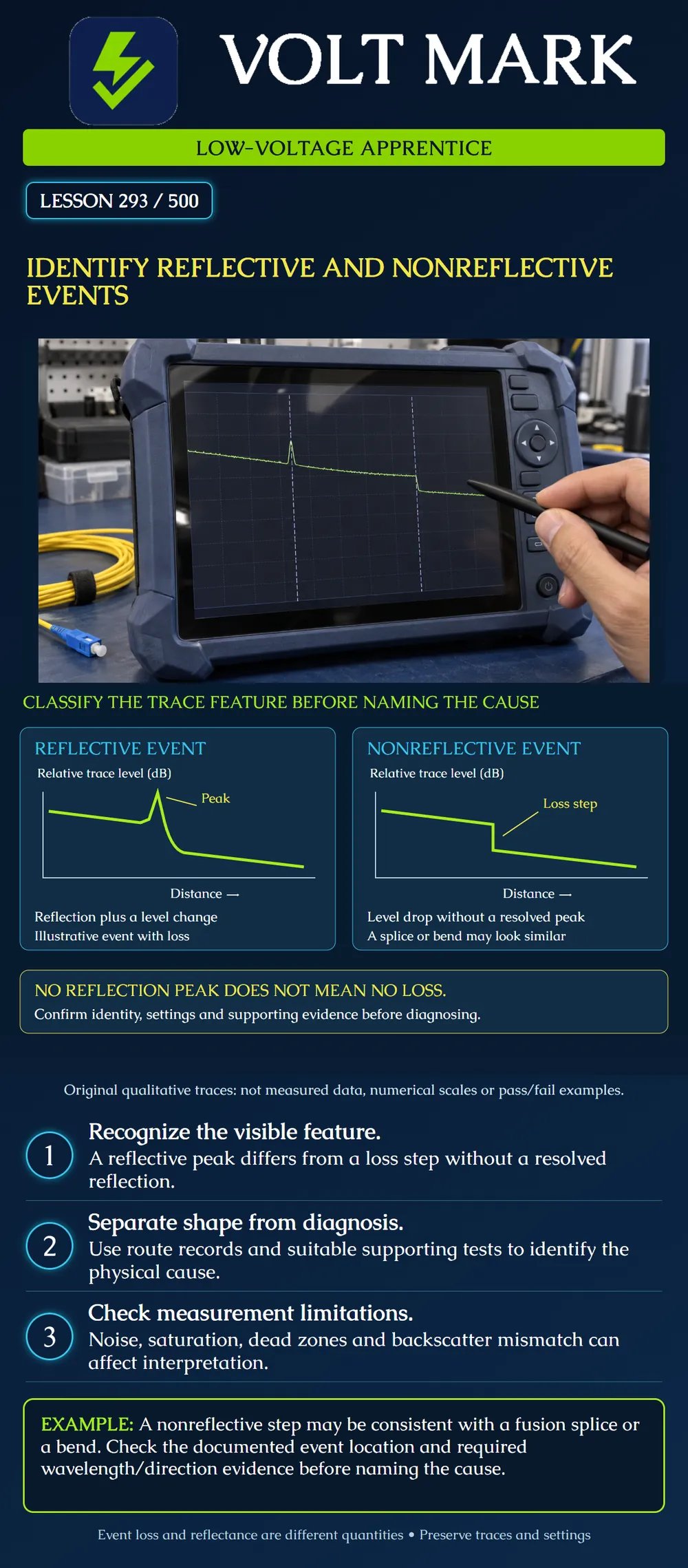
Distinguish a reflective peak from a nonreflective loss step on an OTDR trace. Describe the observed feature separately from a suspected physical cause, and identify evidence needed before accepting a diagnosis.
An OTDR trace plots processed returned-light information against distance. A reflective event can produce a peak above the local backscatter level. A nonreflective loss event can appear as a downward step without a resolved reflection peak. These descriptions classify observed features; they do not uniquely name a component or defect.
Connections involving an optical discontinuity may be reflective. A fusion splice or bend can appear without a distinct reflective peak. Do not assume that every connector must produce a prominent peak, every peak is a defective connector, or every nonreflective step is a splice. The fiber, interface and instrument's ability to resolve a reflection all matter.
The poster's left-hand trace illustrates a reflective event with a lower backscatter level afterward. The peak and the level change convey different information. The peak is associated with reflection; event loss is inferred from appropriate trace regions and the analysis method. Do not use peak height as the event's insertion loss.
The right-hand trace shows a step without a resolved reflection peak. A bend can resemble a fusion splice. Compare the observed location with the actual route and splice records, and use the required wavelength and direction evidence. An unexpected feature is a reason to investigate, not permission to assign a convenient label.
A qualitative diagram is not a measurement. Real event analysis requires suitable signal levels, pulse settings and marker placement. A saturated, flat-topped peak may prevent valid reflectance measurement. Dead zones may hide nearby events or prevent accurate loss evaluation. Noise can obscure small features or produce questionable automatic detections.
Differences in backscatter properties can also affect the inferred event loss. A one-direction apparent gain does not mean a passive joint adds optical energy. Preserve the required opposite-direction evidence and analyze it under the applicable procedure. A missing event in an automatic table must not be turned into an assumed zero-loss result without adequate evidence.
Both original sketches have distance increasing to the right and relative trace level on the vertical axis. The axes deliberately have no numerical ticks. The curves illustrate feature types, not a specific fiber, connector loss, reflectance value or acceptance limit.
On the left, the trace rises into a reflection peak, recovers and continues at a lower level. On the right, the trace steps downward and continues without a visible peak. These are simplified shapes. They do not show every possible event signature, noise behavior or detector response.
The message “no reflection peak does not mean no loss” concerns the right-hand sketch. It does not mean every unexplained drop is a confirmed physical loss event. Setup, backscatter mismatch and trace quality must also be considered.
Use four separate columns: observed feature, suspected cause, supporting evidence, unresolved question. For example: Observed feature: nonreflective downward step. Suspected cause: undetermined; possible bend or joint. Supporting evidence: saved trace, fiber identity and acquisition settings. Unresolved question: whether the route record shows a component at that location and whether other required measurements support the hypothesis.
This structure prevents an early guess from becoming an unsupported permanent diagnosis.
Work first with saved training traces. Mark examples of peaks, steps and unresolved regions. Keep the original traces and settings. Do not deliberately kink or damage an installed cable to create a demonstration. Any instrument use must follow the isolated training setup, optical-safety procedure and actual manufacturer instructions.
What feature suggests a reflective event? A resolved reflection peak. Can a nonreflective event still involve loss? Yes. Is peak height the same as event insertion loss? No. Can a bend resemble a fusion splice? Yes. Does an automatic event label establish the physical cause? No. What can a flat-topped peak indicate? Detector saturation and limited reflectance-measurement validity. Should uncertain observations be preserved? Yes, with their settings and limitations.
A saved training trace has a downward step without a resolved peak. The automatic table calls it a splice, but the route record shows no joint at that location. Work the case in four columns: Observed feature: nonreflective step on this acquisition. Suspected cause: unresolved; a joint or bend remains a possibility. Supporting evidence: retain the trace, fiber identity, settings and the conflicting route record. Unresolved question: does comparison with the required wavelength and opposite-direction evidence support a physical explanation? The resulting report describes the discrepancy and requests investigation. It does not add a splice to the drawing or declare the cable acceptable. Classification of a shape is the first step; identification of its cause needs corroboration.
Fiber Optic Association, OTDR FAQs: https://www.thefoa.org/tech/ref/testing/OTDR/OTDR-FAQS.html Opened, including its cable-kink example and measurement limitations. Used for similar nonreflective appearances and interpretation uncertainty. Deliberate tight bending, generic limits and legacy calibration suggestions are not adopted.
Fiber Optic Association, Measuring Reflectance or Return Loss: https://www.thefoa.org/tech/ref/testing/test/reflectance.html Opened for reflective peaks, saturation and distinction between individual-event reflectance and broader return measurements. Unrelated liquid/mandrel test techniques are not adopted.
Texas journeyman, 15 questions, scored by topic against the 70% mark. No card, and no account needed to start.
Free study material for low-voltage apprentices. This is a national foundation course: requirements differ by state and by local jurisdiction, and a practice that is common in one place is not a rule everywhere. Nothing here is a licence, a certification, or authority to work unsupervised, and completing it does not count as apprenticeship hours or continuing-education credit. Check the codes adopted where you are working, the licensing authority for that work, and your employer's safety programme. VoltMark is not affiliated with, endorsed by, or sponsored by NFPA, OSHA, NICET, BICSI, FOA, or any state or local licensing authority.

Electrician licensing exam prep: practice questions, timed exam simulations, and step-by-step help finding every answer in the NEC.