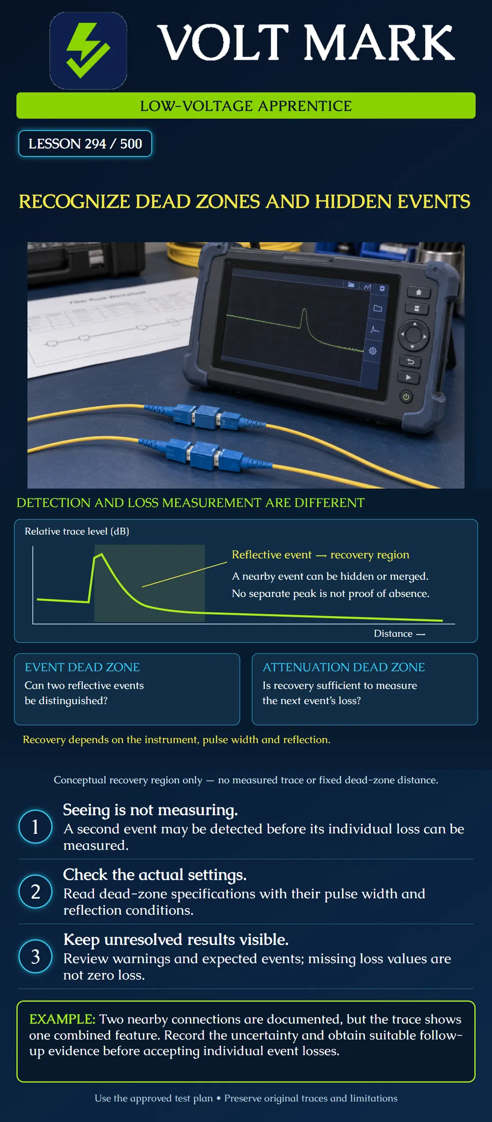
Distinguish event detection from event-loss measurement and recognize when closely spaced components cannot be individually characterized by the current OTDR acquisition. This lesson concerns interpretation, not permission to alter a live fiber system.
After a strong reflection, an OTDR needs time to recover. The displayed distance corresponding to that recovery can conceal nearby features. The event dead zone concerns distinguishing nearby reflective events; the attenuation dead zone concerns recovering sufficiently to measure a following event's loss. Detecting two features therefore does not guarantee two valid loss values. Pulse width and reflection strength affect recovery. Read the measurement conditions attached to a specification rather than treating its shortest quoted distance as a guarantee for every trace. [1]
Fluke's legacy OptiFiber guidance describes a backscatter warning when suitable backscatter cannot be measured. It illustrates why a reflective connection can prevent an individual or overall OTDR loss calculation. An OLTS uses a different technique, so a valid OLTS result does not remove the OTDR's measurement limitation. Preserve both results and evaluate each against the current project's required tests. [2] The old article's standards statements and numerical product examples are not current nationwide acceptance rules.
A campus drawing identifies two connections close together in an equipment room. The acquisition shows one broad feature. The apprentice writes: “One combined feature observed near the documented pair; separate losses not established.” That statement distinguishes evidence from interpretation. Writing “second connection missing,” “zero loss,” or “both pass” would go beyond the trace. The next step is a review of fiber identity, route records and acquisition suitability with the responsible technician. The training case supplies no instrument model, separation or acceptance threshold, so no definite resolution claim is possible.
Software places two event markers near a reflection. One row has a loss value and another has a warning or blank field. The markers do not prove that both losses are valid. Keep the warning and original file. Ask what measurement the software could actually support. Do not substitute a hand-entered zero to make the report look complete. If a later acquisition resolves the region, retain both files and explain what changed rather than silently replacing the earlier evidence.
An operator zooms in on a broad feature and sees more screen pixels. Zoom alone has not acquired new optical information. The team still needs a test setup capable of answering the question. A shorter pulse may help with close spacing but can reduce useful reach; any follow-up acquisition must remain suitable for the link and the approved test objective. Do not trade away coverage of the rest of the link without documenting it. Follow instrument guidance and preserve settings with each file.
For an unresolved region, record the exact fiber and endpoints, wavelength, direction, pulse width, acquisition settings and affected location. Compare the trace with the expected physical event sequence. Ask the qualified lead whether different acquisition settings, a suitable instrument or measurements from the other end would provide useful additional evidence. These are planning options, not a promise that every hidden event can be individually measured. A launch fiber can support near-end characterization; it does not increase the physical spacing between internal connections.
Use a provided training trace rather than a live system. Fill in:
[1] EXFO, Optical Time-Domain Reflectometer (OTDR), glossary sections on event and attenuation dead zones and pulse width. Accessed 2026-10-01. https://www.exfo.com/en/resources/glossary/optical-time-domain-reflectometer-otdr/ [2] Fluke Networks, WARNING: Cannot measure backscatter (OptiFiber), dated 2014-04-04. Accessed 2026-10-01. Used for measurement limitations only; historical standards claims and product distances were not adopted. https://www.flukenetworks.com/knowledge-base/optifiber/warning-cannot-measure-backscatter-optifiber
Texas journeyman, 15 questions, scored by topic against the 70% mark. No card, and no account needed to start.
Free study material for low-voltage apprentices. This is a national foundation course: requirements differ by state and by local jurisdiction, and a practice that is common in one place is not a rule everywhere. Nothing here is a licence, a certification, or authority to work unsupervised, and completing it does not count as apprenticeship hours or continuing-education credit. Check the codes adopted where you are working, the licensing authority for that work, and your employer's safety programme. VoltMark is not affiliated with, endorsed by, or sponsored by NFPA, OSHA, NICET, BICSI, FOA, or any state or local licensing authority.

Electrician licensing exam prep: practice questions, timed exam simulations, and step-by-step help finding every answer in the NEC.