Recognize an OTDR gainer as a measurement effect and distinguish it from evidence of a low-loss splice. Calculate a signed bidirectional estimate for a valid matched event without turning that estimate into an unsupported pass declaration.
An OTDR infers loss from returning light. Fibers on opposite sides of a splice can return different proportions of backscatter, including when their nominal fiber type is the same. A higher return after the splice may produce an upward trace step and a negative reported event loss. This apparent gain does not mean a passive splice amplifies transmitted power. In the reverse direction, the same mismatch can make the event loss appear too large. [1]
For a properly measured singlemode splice, averaging opposite-direction event-loss readings reduces the backscatter mismatch error. Preserve the algebraic signs. Both measurements must belong to the same physical event and wavelength; an unresolved event does not become a valid zero. The result remains a measurement estimate with uncertainty, not an absolute guarantee. FOA explains this directional backscatter effect and the use of bidirectional averaging for singlemode splice loss. [2]
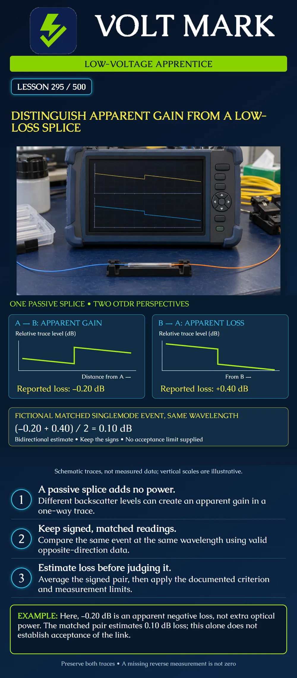
The left trace is viewed from endpoint A and shows an upward step. The right trace is viewed from endpoint B and shows a downward step. Each horizontal axis runs away from the measuring end. The traces are conceptual; their heights do not establish a numerical vertical scale. The reported values beneath them supply the arithmetic: A to B: −0.20 dB. B to A: +0.40 dB. Sum: +0.20 dB. Divide by two: +0.10 dB estimated loss. The minus sign must stay in the sum. Replacing −0.20 with +0.20 would produce 0.30 dB, an incorrect answer for these supplied data. None of these figures is a universal splice allowance.
A training report contains the fictional pair shown on the poster. An apprentice proposes re-splicing immediately because the reverse reading looks larger than expected. Another proposes accepting the splice because the forward reading appears better than zero. Neither conclusion follows from one directional value. The review should first establish identity, valid acquisition and the applicable acceptance criterion. The exercise asks learners to separate three statements:
“Low-loss splice” should describe a supported measurement relative to the applicable requirement, not an upward trace shape. For example, a small positive matched estimate could support that description if the measurement is valid and the criterion is met. A gainer alone supplies no such proof. An unusual result may also merit review for noise, event matching or dead-zone limitations. Do not label every unexpected trace feature as a gainer simply because the term is familiar.
Assume each pair below is from one validly matched singlemode splice at the same wavelength. These are arithmetic exercises, not field acceptance examples.
Record the fiber identifier, named endpoints, wavelength and physical splice identification. Add each original trace filename and its acquisition direction. Record the signed readings separately and state whether the event was resolved adequately in both traces. Then show the sum and mean, identify the applicable criterion, and document the reviewer's disposition. Keep any warning beside the result. A later corrected match should include an explanation so another technician can reconstruct the decision.
[1] Fluke Networks, Cable Testing 101: There's No Gain with “Gainers,” October 13, 2016. Accessed 2026-10-01. Used for backscatter mismatch and directionality; historical application budgets and broad standards language were not adopted. https://www.flukenetworks.com/blog/cabling-chronicles/cable-testing-101-theres-no-gain-gainers [2] Fiber Optic Association, The FOA Reference for Fiber Optics — OTDRs, measurement uncertainty section. Accessed 2026-10-01. Used for singlemode splice measurement interpretation and bidirectional averaging. https://www.foa.org/tech/ref/testing/OTDR/OTDR.html
Texas journeyman, 15 questions, scored by topic against the 70% mark. No card, and no account needed to start.
Free study material for low-voltage apprentices. This is a national foundation course: requirements differ by state and by local jurisdiction, and a practice that is common in one place is not a rule everywhere. Nothing here is a licence, a certification, or authority to work unsupervised, and completing it does not count as apprenticeship hours or continuing-education credit. Check the codes adopted where you are working, the licensing authority for that work, and your employer's safety programme. VoltMark is not affiliated with, endorsed by, or sponsored by NFPA, OSHA, NICET, BICSI, FOA, or any state or local licensing authority.

Electrician licensing exam prep: practice questions, timed exam simulations, and step-by-step help finding every answer in the NEC.