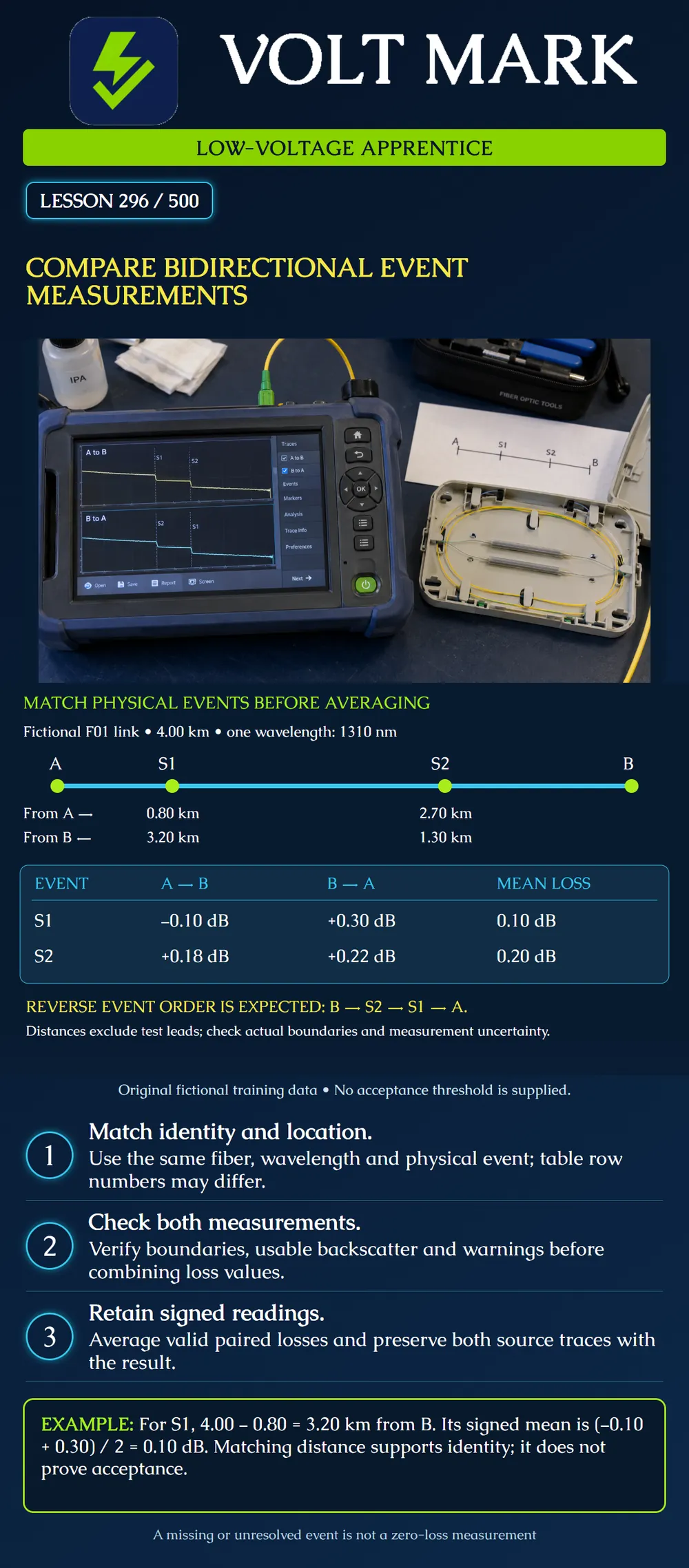
Match the same physical event in opposite-direction OTDR measurements, check whether both readings are usable, and calculate a signed mean without confusing event order, distance references or wavelengths.
Backscatter differences can bias a one-way OTDR event-loss result. Combining valid opposite-direction readings helps reduce that bias. For connector comparisons, preserve the mated test-cord-to-link connections in the approved bidirectional procedure so that the same interfaces are measured. Fluke's guidance describes moving the instrument to the other end while those interfaces remain in place. [1] Use the current equipment workflow and authorized test plan; this lesson is not permission to disconnect operational equipment.
Launch and receive fibers provide backscatter needed to characterize the link's end connections. Their lengths can be included in uncorrected distance readings. Manufacturer guidance describes compensation and checking the selected boundary events. [2] Before comparing locations, identify whether each distance starts at an instrument port or the installed-link endpoint. Retain the installed-link end connections in the intended measurement boundary. Do not subtract a test lead twice.
The fictional installed fiber F01 is 4.00 km long. All example event-loss readings are at 1310 nm. Test-lead lengths have already been excluded from the displayed distances. From A, the physical order is A, S1, S2, B. From B, the order is B, S2, S1, A. S1 is 0.80 km from A and therefore 3.20 km from B. S2 is 2.70 km from A and therefore 1.30 km from B. Both pairs sum to 4.00 km. This simple arithmetic is a location cross-check for the stated assumptions, not proof of identity by itself. Real measurements have uncertainty; fiber length is also different from a surveyed straight-line map distance.
For S1, use −0.10 dB from A and +0.30 dB from B: (−0.10 + 0.30) / 2 = 0.10 dB. For S2, use +0.18 dB from A and +0.22 dB from B: (0.18 + 0.22) / 2 = 0.20 dB. Retain the signs. These are estimated event losses from the supplied data, not universal limits. The poster intentionally contains no pass/fail column because no acceptance criterion has been provided.
An apprentice copies the first internal-event row from each direction and averages the two values. In this example, the first internal event from A is S1; the first from B is S2. The resulting number would combine two different physical splices. Correct arithmetic cannot repair that identification error. Pair the physical event using the endpoint names, route information, normalized distance and trace features. Do not assume reverse files will contain the same number of automatically detected events.
S1 is resolved from A, but the reverse acquisition cannot separately characterize it near another feature. Keep the valid forward reading and the reverse warning. Do not enter zero, copy a neighboring event's value or halve the forward reading. Document that the paired result is unresolved and arrange suitable follow-up with the responsible technician. A mathematically complete spreadsheet is not a substitute for a complete measurement.
Two filenames look similar, but one is at 1310 nm and the other at 1550 nm. They may be useful for a separate wavelength comparison; they are not the matched wavelength pair required for this exercise. Preserve the wavelength with every directional result. Likewise, readings from F01 and F02 cannot be combined merely because the cables follow the same route.
For each physical event record:
A training link is 5.00 km with an event 1.25 km from A. Under the same normalized-distance assumptions, it is 3.75 km from B. Valid event-loss readings are −0.06 dB and +0.22 dB; their mean is 0.08 dB. No pass/fail conclusion follows without the applicable requirement and measurement review.
[1] Fluke Networks, Bi-Direction Testing with an OTDR, November 17, 2016. Accessed 2026-10-01. Used for measurement pairing and preserving test interfaces. Historical standards quotations are not presented as a current nationwide mandate. https://www.flukenetworks.com/blog/cabling-chronicles/bi-direction-testing-otdr [2] Fluke Networks, Setting the Launch Fiber Compensation — DTX Compact OTDR Module, March 3, 2014. Accessed 2026-10-01. Used for boundary concepts; model-specific menu instructions are not generalized. https://www.flukenetworks.com/knowledge-base/dtx-compact-otdr/setting-launch-fiber-compensation-dtx-compact-otdr-module
Texas journeyman, 15 questions, scored by topic against the 70% mark. No card, and no account needed to start.
Free study material for low-voltage apprentices. This is a national foundation course: requirements differ by state and by local jurisdiction, and a practice that is common in one place is not a rule everywhere. Nothing here is a licence, a certification, or authority to work unsupervised, and completing it does not count as apprenticeship hours or continuing-education credit. Check the codes adopted where you are working, the licensing authority for that work, and your employer's safety programme. VoltMark is not affiliated with, endorsed by, or sponsored by NFPA, OSHA, NICET, BICSI, FOA, or any state or local licensing authority.

Electrician licensing exam prep: practice questions, timed exam simulations, and step-by-step help finding every answer in the NEC.