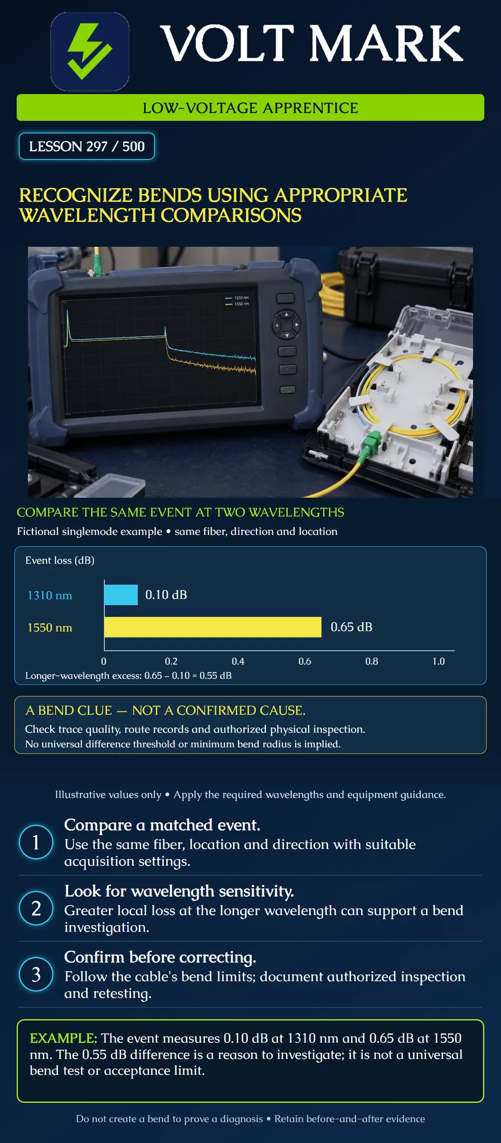
Use a suitable wavelength comparison to identify a possible bend-related loss event while separating a diagnostic clue from a confirmed physical cause and an acceptance decision.
A bend can produce more local loss at a longer test wavelength. Fluke's troubleshooting guidance describes wavelength comparisons such as 1310 and 1550 nm for singlemode fiber, or 850 and 1300 nm for multimode fiber. [1] The poster uses a singlemode example only. Select wavelengths appropriate to the installed fiber, equipment and required test plan. Do not apply a singlemode example automatically to every fiber system.
Match the same event on the same fiber and in the same direction. Check that both acquisitions resolve the location adequately. Compare local event loss; a whole-link loss difference also includes distributed fiber attenuation and other events. Different launch conditions, unsuitable settings, noise or incorrect event matching can undermine an interpretation. A manufacturer's automatic bend flag should be reviewed with its criteria and the actual trace.
The cyan bar represents 0.10 dB local event loss at 1310 nm. The yellow bar represents 0.65 dB at 1550 nm. Both bars start at zero and use the same scale. The difference is: 0.65 dB − 0.10 dB = 0.55 dB. This is a comparison between wavelengths, not the bidirectional average taught in lesson 296. The graphic does not provide a universal threshold. It shows why a technician might investigate the event location for a bend or other stress. Neither bar measures bend radius, and the difference does not identify a specific enclosure or cable-management defect on its own.
A campus fiber has a new local loss feature near a documented tray location. The matched longer-wavelength trace shows more loss at that feature. The apprentice's report states: “Wavelength-sensitive event near the recorded tray; possible bend-related stress; physical cause unconfirmed.” This is a useful observation. “The tray is definitely pinching the fiber” would be premature without authorized inspection and supporting evidence. Keep the original files and route information with the report.
One record is F01 measured from Building A at 1310 nm. The second is F02 measured from Building B at 1550 nm. Even if both records have an event around the same displayed distance, they are not a matched wavelength comparison. Correct fiber identity and direction first. The exercise is about evidence quality, not finding a convenient pair of numbers that supports a preferred diagnosis.
A learner sees a lower total link loss at 1550 nm and concludes there cannot be a local bend. That conclusion is unsupported. The question concerns the same local event at each wavelength; total link loss combines multiple contributions. Inspect the relevant event and the measurement quality. Conversely, a higher whole-link loss at one wavelength does not automatically locate a bend.
Corning's duct-installation guidance distinguishes loaded bend-radius requirements during installation from installed requirements and directs users to the specific cable specification. It also warns that excessive bending, pulling or crushing can damage the cable. [2] Use the correct product and operating condition; do not borrow a generic diameter multiplier from an unrelated cable. A bend-insensitive fiber designation does not replace the cable or assembly instructions. Never deliberately kink, tighten or manipulate an installed fiber to make an event more obvious.
The responsible technician should plan authorized access and any correction using the manufacturer's guidance. Preserve the original state and records. If an authorized correction is made, retain comparable before-and-after acquisitions at the required wavelengths, and complete any other required acceptance tests. Improvement at one event does not prove that the entire link now meets all requirements. If the evidence remains ambiguous, report the uncertainty rather than forcing a bend label.
Record the fiber ID, endpoint, acquisition direction, wavelength and trace filename. Identify the local event with its distance reference and supporting route record. Note pulse width, range, acquisition quality, warnings and event resolution. Record both event-loss values and their difference, if meaningful. Add the proposed inspection location, responsible person, relevant product bend specification and disposition. Preserve any retest alongside its original record.
Answer: 0.35 dB. It is not an automatic pass/fail verdict.
Answer: No.
Answer: No.
Answer: No; use authorized investigation and product instructions.
Answer: Only after the complete required measurements and review satisfy the applicable criteria.
[1] Fluke Networks, OTDR — Optical Time Domain Reflectometer, troubleshooting section. Accessed 2026-10-01. Used for wavelength-dependent bend investigation; exact-location marketing claims and universal diagnosis claims were not adopted. https://www.flukenetworks.com/expertise/learn-about/otdr [2] Corning, Standard Recommended Procedure 005-011, Issue 17, June 2019, Duct Installation of Fiber Optic Cable, cable-handling precautions. Accessed 2026-10-01. Used for product-specific loaded versus installed bend limits, not universal numeric limits. https://www.corning.com/content/dam/corning/catalog/coc/documents/standard-recommended-procedures/005-011.pdf
Texas journeyman, 15 questions, scored by topic against the 70% mark. No card, and no account needed to start.
Free study material for low-voltage apprentices. This is a national foundation course: requirements differ by state and by local jurisdiction, and a practice that is common in one place is not a rule everywhere. Nothing here is a licence, a certification, or authority to work unsupervised, and completing it does not count as apprenticeship hours or continuing-education credit. Check the codes adopted where you are working, the licensing authority for that work, and your employer's safety programme. VoltMark is not affiliated with, endorsed by, or sponsored by NFPA, OSHA, NICET, BICSI, FOA, or any state or local licensing authority.

Electrician licensing exam prep: practice questions, timed exam simulations, and step-by-step help finding every answer in the NEC.