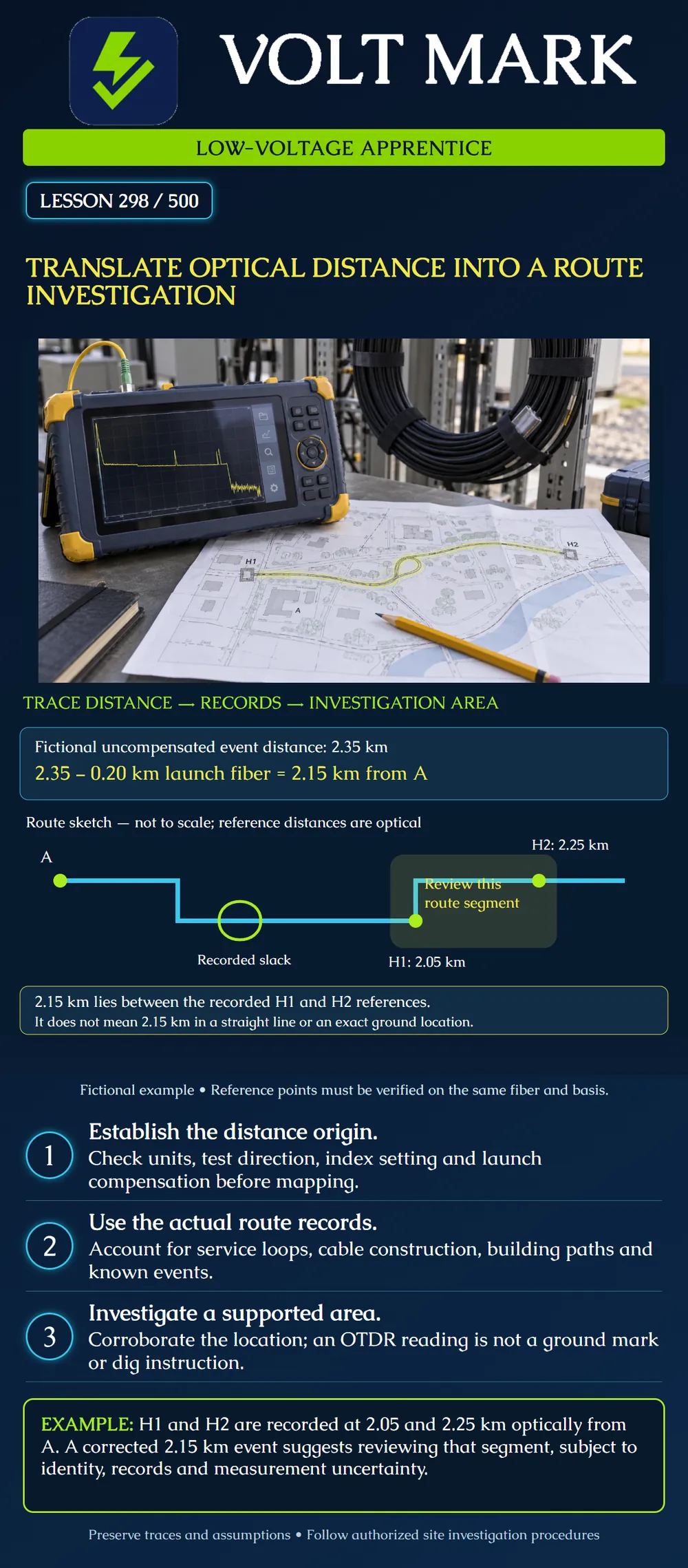
Convert an OTDR location into a supported route investigation by checking its distance origin, using documented reference events and retaining uncertainty.
An OTDR estimates distance along the optical fiber using travel time and the configured refractive-index value. It does not directly survey the cable jacket or the ground route. Fluke explains that an incorrect index setting changes reported length and that fiber can be longer than its cable jacket. [1] Route distance can also differ because of service loops, indoor pathways, vertical runs and routing turns. Keep these concepts separate when discussing a location.
FOA's restoration guide emphasizes current route maps, component identification, photographs and original test records. It distinguishes fiber length from cable length and describes extra cable stored in service loops. [2] These records let a technician compare a new event with known locations. The guide's generic excess-fiber percentage is not used as a universal correction here. Use product information and verified installation records.
The instrument reports an event at 2.35 km from its port. For this example only, that display includes a verified 0.20 km optical launch-fiber distance. Therefore: 2.35 − 0.20 = 2.15 km optically from endpoint A. This subtraction is appropriate because the stated reading is uncompensated. If the instrument already reports 2.15 km from A after compensation, subtracting the launch fiber again would be wrong.
The record identifies two reference events on the same fiber and distance basis: H1: 2.05 km optically from A. H2: 2.25 km optically from A. The corrected event lies between them. The optical offsets are 0.10 km after H1 and 0.10 km before H2. These equal optical offsets do not establish a geographic midpoint. The drawing is a conceptual route sketch, not a surveyed map, and the shaded segment is an investigation area rather than a precise fault mark.
A learner measures 2.35 km along a site map from the building and identifies a road crossing as the fault location. The trace began at an instrument port with a launch fiber, and the map contains undocumented stored cable. The apparent precision is unsupported. First normalize the distance origin, verify the route and reconcile known reference events. State what is known and what remains uncertain before assigning an investigation area.
A report already has launch compensation enabled. Its event location is 2.15 km from the installed-link endpoint. An apprentice subtracts 0.20 km and reports 1.95 km. The arithmetic is valid but the reference convention is wrong. Read the report settings and marker assignments before transforming a number. Keep the original reading and each correction in the work record so another technician can reproduce the result.
A route record shows stored cable near an enclosure. Distance consumed inside that loop does not advance the route by the same amount on a map. An event near a loop therefore cannot be mapped by assuming every meter of fiber corresponds to a meter farther along the roadway. Confirm the actual loop, cable and fiber identification through authorized investigation. Do not cut, uncoil or disturb cable merely to force the records to agree.
Identify the fiber, cable, endpoint and test direction. State the wavelength, index setting, units and distance convention. Record the event feature and any resolution limitation. List the verified reference events that bracket it, the source of the route records, known slack and unresolved discrepancies. Give the responsible team an investigation segment with the evidence that supports it. If reference identity or uncertainty prevents reliable bracketing, broaden or defer the location claim instead of inventing a narrow boundary.
Compare an earlier trace where available and corroborate from the opposite end when the authorized test plan and link condition allow it. Different directions use different origins. Cable markings and surveyed route information may add evidence, but none should be silently substituted for optical distance. Do not change the index setting solely to make a trace fit a desired map position. Document justified configuration corrections and retain the earlier record.
A fictional uncompensated reading is 1,780 m. The verified optical launch distance is 150 m. The corrected distance is 1,630 m from the link endpoint. Reference events are recorded at 1,580 m and 1,710 m on the same basis. The event is 50 m beyond the first and 80 m before the second, optically. This identifies a candidate segment, not a point to excavate.
[1] Fluke Networks, Manual Cable Settings — OptiFiber, April 2, 2014. Accessed 2026-10-01. Used for index-related distance error and fiber versus cable length; old numeric defaults and device menus are not generalized. https://www.flukenetworks.com/knowledge-base/optifiber/manual-cable-settings-optifiber [2] Fiber Optic Association, Restoration Guide, copyright 2019, documentation and route-mapping sections. Accessed 2026-10-01. Used for records, reference testing and service-loop context; generic length percentages and historical instrument limitations were not adopted. https://www.thefoa.org/tech/guides/RG.pdf
Texas journeyman, 15 questions, scored by topic against the 70% mark. No card, and no account needed to start.
Free study material for low-voltage apprentices. This is a national foundation course: requirements differ by state and by local jurisdiction, and a practice that is common in one place is not a rule everywhere. Nothing here is a licence, a certification, or authority to work unsupervised, and completing it does not count as apprenticeship hours or continuing-education credit. Check the codes adopted where you are working, the licensing authority for that work, and your employer's safety programme. VoltMark is not affiliated with, endorsed by, or sponsored by NFPA, OSHA, NICET, BICSI, FOA, or any state or local licensing authority.

Electrician licensing exam prep: practice questions, timed exam simulations, and step-by-step help finding every answer in the NEC.