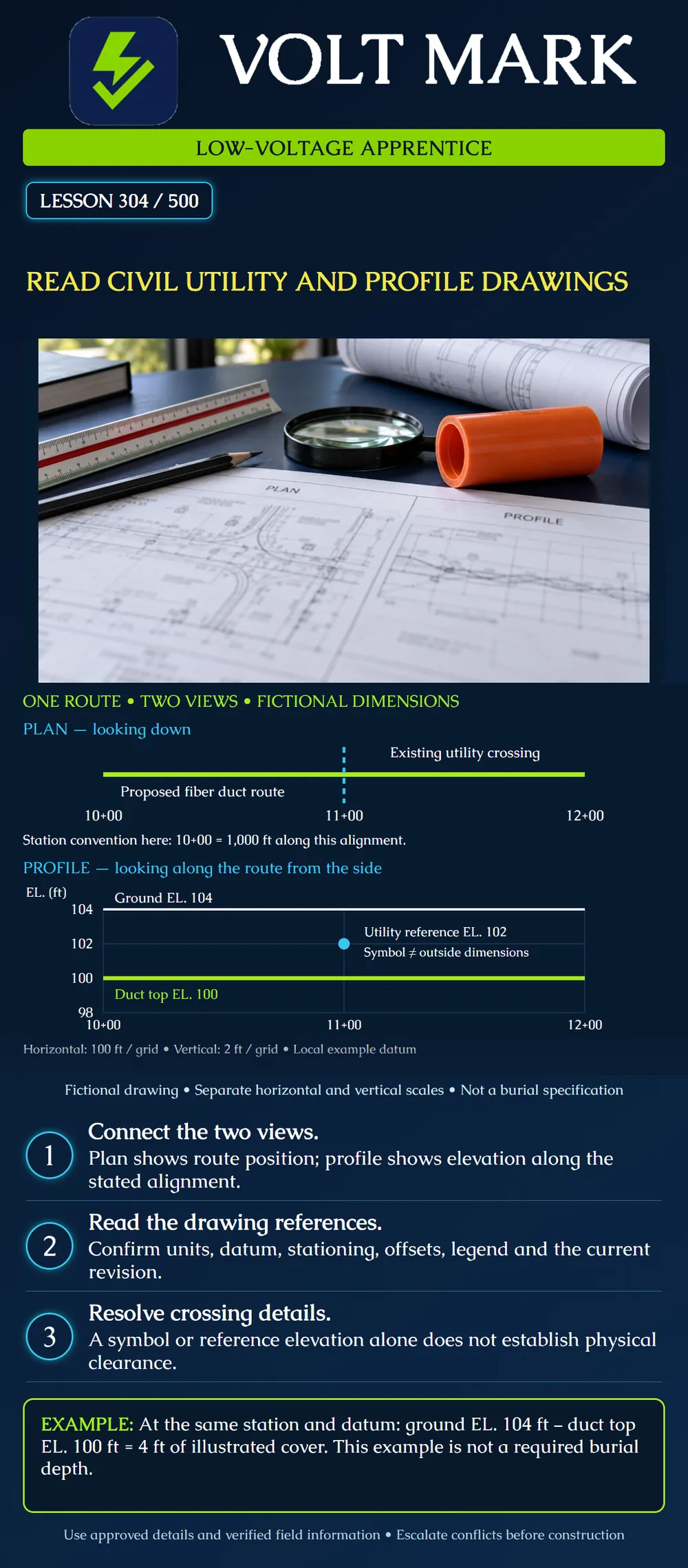
Connect a fiber-route plan to its profile, interpret a stated station convention and elevation reference, and identify missing information that prevents construction decisions. This is drawing literacy, not authorization to design, survey or excavate.
All elevations shown use one fictional local datum. At station 11+00, ground is EL. 104 feet and the duct top is EL. 100 feet. Subtracting those corresponding elevations gives 4 feet of illustrated cover. It is neither a code minimum nor a suitable installation depth for a real site. Confirm whether actual plans reference existing grade, final grade, duct top, duct centerline, invert or another defined surface.
The existing utility symbol is centered at a reference elevation of 102 feet. That is not enough to compute outside-to-outside clearance. Its size, the meaning of the reference elevation, the accuracy of its location and the relevant approved crossing detail remain unknown. The diagram deliberately avoids assigning a physical diameter to the symbol. An apparent gap is not a clearance approval.
First record the drawing number, revision, issue purpose, alignment name, units, legend, datum and control notes. Find match lines and referenced sections so the route does not stop at the edge of one sheet. Read specifications and details associated with the work.
Then follow one feature across the views. For a handhole, identify its plan location and offset from the named alignment, then locate its profile information and the relevant installation detail. Do not assume a roadway centerline profile represents the elevation at an offset fiber route. Confirm what the profile actually describes.
Finally list uncertainties before work begins. Examples include different revisions between sheets, an unreferenced elevation, a utility shown in plan but absent from profile, or a crossing without verified outside dimensions. Refer the conflict to the responsible designer or supervisor through the project's clarification process. Record the response and authorized revision.
On an invented sheet, a handhole is at 12+40 and a second is at 13+10, with the same feet-based alignment and no station equation between them. The station difference is 1,310 − 1,240 = 70 feet. That is an alignment interval; it does not include a cable's slack loops, vertical entries or route offsets.
On another invented profile, final grade is EL. 207.50 feet and duct top is EL. 203.25 feet at the same station and datum. Illustrated cover is 4.25 feet. If the duct elevation instead means centerline, that subtraction is not cover to the top. Obtain the outside geometry and correct reference before answering.
For a practice worksheet, record: sheet and revision; alignment and station; offset; existing or proposed status; elevation reference; datum and units; related detail; uncertainty; responsible reviewer. Use training drawings only. Do not transfer these invented values into field instructions.
Use the poster's fictional station 11+00. First confirm the two elevations share the same station, datum and feet units. Ground is EL. 104 and the defined duct top is EL. 100, so illustrated cover is 104 - 100 = 4 feet. Label that result as the drawing's illustrated cover, not a required minimum. The nearby utility's reference elevation of 102 does not establish its outside surface, so 102 - 100 cannot be reported as verified utility clearance. Record the missing utility dimensions, elevation definition and crossing detail for clarification.
MnDOT, Sample Plan: Profiles narrative and checklist, revision information 2018–2019: https://www.dot.state.mn.us/metro/finaldesign/pdf/sampleplan/profile.pdf Used for profile concepts, vertical control, alignment designation, station/elevation information and checking existing/proposed utility crossings. Its Minnesota roadway examples are not nationwide fiber-installation requirements.
TxDOT, PS&E Preparation Manual, 3.1 Standard Traditional Plan Sheets: https://www.txdot.gov/manuals/des/pse/chapter-3--plan-set-development/section-1--standard-traditional-plan-sheets.html Used only for the plan/profile relationship to horizontal and vertical alignment. State-specific sheet conventions are not generalized.
Texas journeyman, 15 questions, scored by topic against the 70% mark. No card, and no account needed to start.
Free study material for low-voltage apprentices. This is a national foundation course: requirements differ by state and by local jurisdiction, and a practice that is common in one place is not a rule everywhere. Nothing here is a licence, a certification, or authority to work unsupervised, and completing it does not count as apprenticeship hours or continuing-education credit. Check the codes adopted where you are working, the licensing authority for that work, and your employer's safety programme. VoltMark is not affiliated with, endorsed by, or sponsored by NFPA, OSHA, NICET, BICSI, FOA, or any state or local licensing authority.

Electrician licensing exam prep: practice questions, timed exam simulations, and step-by-step help finding every answer in the NEC.