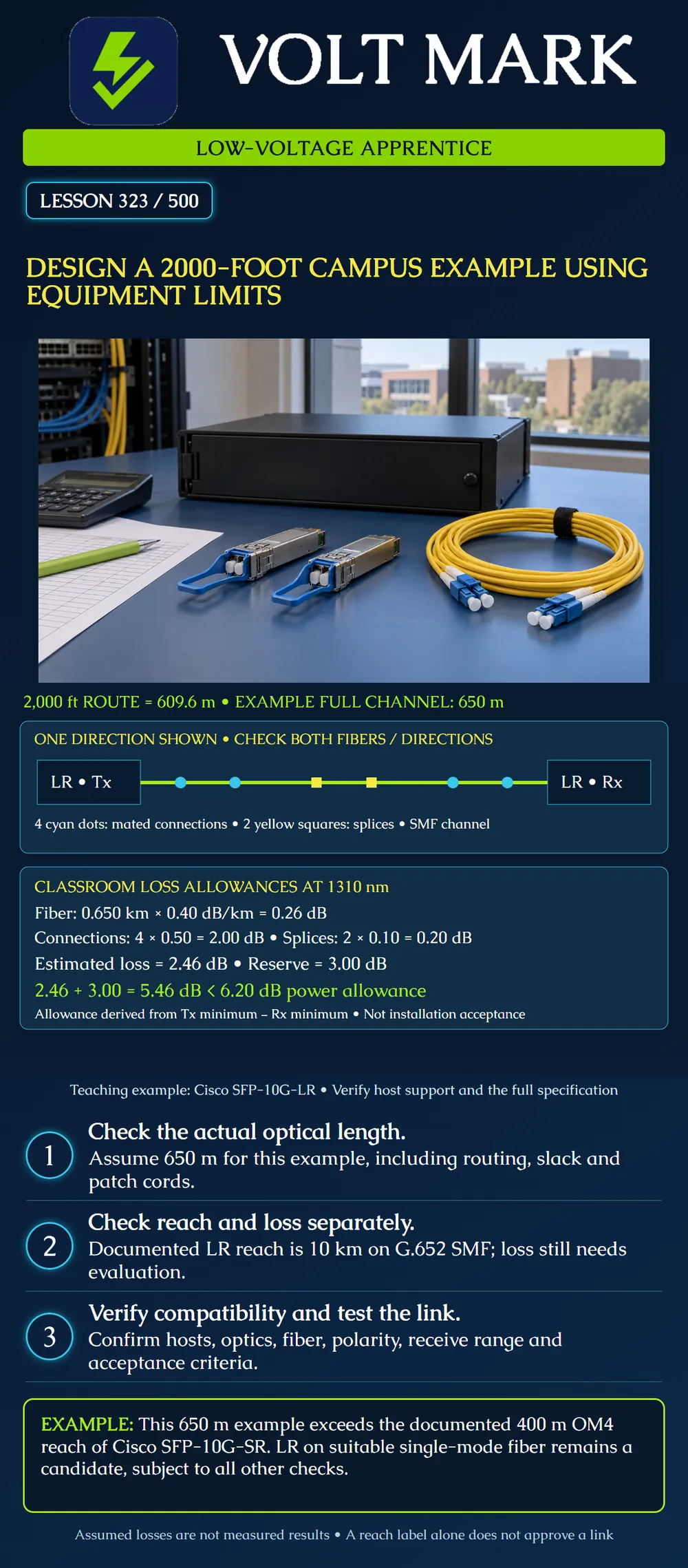
Evaluate a fictional 10 Gb/s campus link using a documented optical-module example, a full-channel length and a transparent loss calculation.
Two buildings need a duplex 10 Gigabit Ethernet connection. The route distance is 2,000 ft, equal to 609.6 m. For this exercise only, assume the complete fiber channel is 650 m after accounting for additional routing, slack and patch cords. The extra 40.4 m is an invented project input, not a standard allowance.
Use a compatible G.652 single-mode channel and consider Cisco SFP-10G-LR at each end. The exact switches, ports and software remain to be verified against the vendor compatibility information. The exercise proposes a candidate optical design; it does not approve equipment for an unidentified host.
Cisco lists SFP-10G-LR at 1310 nm on G.652 single-mode fiber with 10 km reach. Its table gives minimum transmit power of -8.2 dBm and minimum receive power of -14.4 dBm; maximum transmit and receive power are both +0.5 dBm. The derived difference between the minimum values is 6.2 dB.
For comparison, the documented SFP-10G-SR reach on OM4 is 400 m. A 650 m channel exceeds that reach even if its measured attenuation looks low. Do not use a favorable loss result to waive a bandwidth/distance requirement.
The following are classroom allowances, not measured values or universal acceptance limits:
Fiber: 0.650 km × 0.40 dB/km = 0.26 dB. Connections: 4 × 0.50 dB = 2.00 dB. Splices: 2 × 0.10 dB = 0.20 dB. Estimated physical channel loss: 0.26 + 2.00 + 0.20 = 2.46 dB. Loss plus reserve: 2.46 + 3.00 = 5.46 dB. Derived power allowance: -8.2 - (-14.4) = 6.20 dB. Remaining arithmetic headroom after reserve: 6.20 - 5.46 = 0.74 dB.
The estimate fits this screening calculation. The 3 dB reserve is not a component inserted into the channel, and the remaining 0.74 dB is not a guarantee of future performance. Confirm all applicable channel specifications, penalties and project criteria before treating a power calculation as a design decision.
At minimum transmit power and the assumed physical loss: -8.2 dBm - 2.46 dB = -10.66 dBm. If the whole 3.00 dB reserve were consumed as added loss, the example becomes -13.66 dBm, still above the stated minimum receive level.
Also check the high-power end. For these particular module limits, maximum launch power does not exceed maximum receive power even at zero channel attenuation. Do not transfer that conclusion to different optics. Long-reach modules can have different attenuation requirements. Actual receiver levels and link behavior still require verification.
Verify host/port/software support, matching optical interfaces, appropriate fiber and connector arrangements, transmit-to-receive polarity, operating environment and the actual component inventory. Confirm the vendor's complete channel requirements and the project's test plan. Obtain measured results for each required fiber and direction, compare them to the approved criteria and retain the original records.
Optical feasibility does not approve building entries, cable ratings, pathways, bonding details or route permissions. Those design items remain part of the complete campus project.
The channel inventory gains two additional mated connections. At the same assumed 0.50 dB each, they add 1.00 dB: 2.46 + 1.00 + 3.00 = 6.46 dB. That exceeds the 6.20 dB screening allowance by 0.26 dB.
Revisit the proposed design with the responsible team. Do not silently remove the reserve or invent lower component losses to force a passing result. Revised assumptions need evidence and approval.
Answer: The route figure may omit routing, slack and patch-cord contributions.
Answer: No; loss, compatibility and other limits still apply.
Answer: 2.46 dB.
Answer: 0.74 dB.
Answer: No; the revised total is 6.46 dB, above the screening allowance.
Keep the fictional 650 m channel, two splices and all stated allowances, but add only one mated connection to the original four. Calculate physical loss, loss plus reserve, remaining screening headroom and estimated receive power at minimum launch before consuming reserve. Does this arithmetic alone approve the link?
Answer guide: Physical loss is 2.46 + 0.50 = 2.96 dB. Including reserve gives 5.96 dB. Remaining screening headroom is 6.20 - 5.96 = 0.24 dB. Estimated receive power before reserve consumption is -8.2 - 2.96 = -11.16 dBm. The arithmetic fits this screen, but complete vendor requirements, host compatibility and the approved test/acceptance process still apply.
Accessed 2026-10-01. Cisco, 10GBASE SFP+ Modules Data Sheet, tables 3 and 4 and platform/connector notes: https://www.cisco.com/c/en/us/products/collateral/interfaces-modules/transceiver-modules/data_sheet_c78-455693.html Used for the named module reach, fiber type, power range and compatibility caveats. No extended engineered-link exception is invoked. The 6.2 dB number here is explicitly derived from the LR power specifications, not taken from another model's footnote.
Texas journeyman, 15 questions, scored by topic against the 70% mark. No card, and no account needed to start.
Free study material for low-voltage apprentices. This is a national foundation course: requirements differ by state and by local jurisdiction, and a practice that is common in one place is not a rule everywhere. Nothing here is a licence, a certification, or authority to work unsupervised, and completing it does not count as apprenticeship hours or continuing-education credit. Check the codes adopted where you are working, the licensing authority for that work, and your employer's safety programme. VoltMark is not affiliated with, endorsed by, or sponsored by NFPA, OSHA, NICET, BICSI, FOA, or any state or local licensing authority.

Electrician licensing exam prep: practice questions, timed exam simulations, and step-by-step help finding every answer in the NEC.