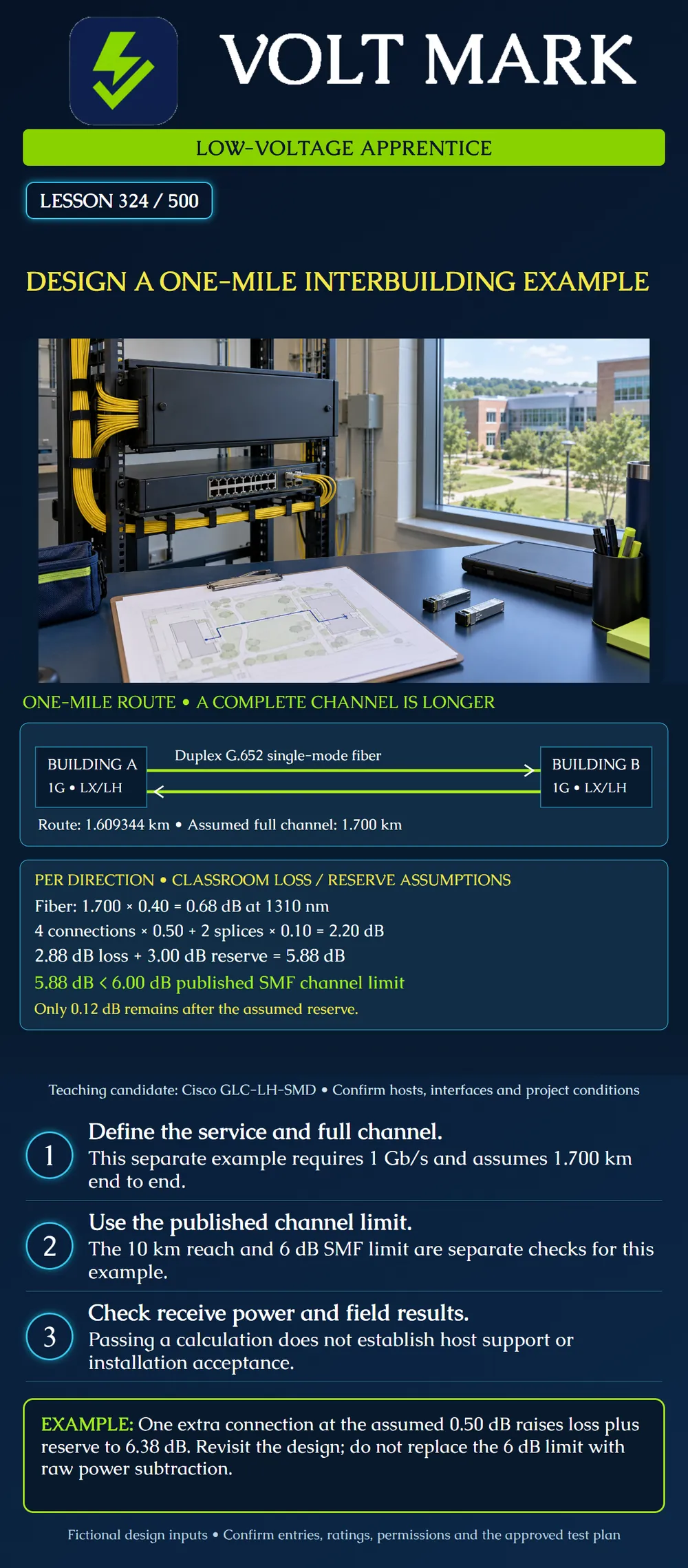
Evaluate a fictional one-mile interbuilding link using a published channel-loss limit, a separate receiver-power check and documented project assumptions.
This is a separate 1 Gb/s exercise, not a replacement for lesson 323's 10 Gb/s requirement. Two buildings need a duplex Gigabit Ethernet connection. One international mile is 5,280 ft or 1.609344 km. Assume a complete 1.700 km channel in each direction after additional routing, slack and patch cords. The additional 90.656 m is an invented exercise input, not a prescribed allowance.
Consider Cisco GLC-LH-SMD modules with compatible host ports and G.652 single-mode fiber. Actual host and software support remain to be confirmed. The two fibers provide opposite transmission directions; they are not two physically diverse routes.
Cisco's Gigabit SFP data sheet lists LX/LH reach of 10 km on single-mode fiber and a 6 dB maximum channel insertion-loss entry for G.652. It separately lists transmit power from -9.5 to -3 dBm and receive power from -20 to -3 dBm. Both channel-loss and receiver specifications matter.
Subtracting minimum receive power from minimum transmit power gives 10.5 dB. That number does not replace the published 6 dB channel entry. The sheet notes that additional loss may be allowed at shorter distances; this exercise does not invoke that possibility or invent an alternate approved limit.
Use these classroom values at 1310 nm: Fiber: 1.700 km at 0.40 dB/km. Mated connections: four at 0.50 dB each. Splices: two at 0.10 dB each. Additional design reserve: 3.00 dB.
A mated connection is counted once, not once for each connector half. Confirm the inventory and reference boundaries in a real channel. These allowances are not universal component limits or measured acceptance results.
Fiber loss = 1.700 × 0.40 = 0.68 dB. Connection loss = 4 × 0.50 = 2.00 dB. Splice loss = 2 × 0.10 = 0.20 dB. Estimated physical loss = 0.68 + 2.00 + 0.20 = 2.88 dB. Loss plus reserve = 2.88 + 3.00 = 5.88 dB. Remaining space below the selected 6.00 dB ceiling = 0.12 dB.
The assumed length is below the documented reach and the calculation fits the selected ceiling. The remaining space after reserve is small. Preserve the reserve as a declared design assumption; do not describe it as physical loss already measured in the cable.
At minimum transmit power with the estimated physical loss: -9.5 dBm - 2.88 dB = -12.38 dBm. If the entire reserve becomes additional loss: -9.5 dBm - 5.88 dB = -15.38 dBm. Both values are above the stated minimum receive level.
For the high-power side, this module's maximum launch power equals its maximum receive input. A passive nonnegative channel loss does not raise received power above that launch value. Verify the complete specifications and actual receive levels rather than copying this conclusion to other optics.
The route gains one additional mated connection at the assumed 0.50 dB: 2.88 + 0.50 + 3.00 = 6.38 dB. The result exceeds the selected ceiling by 0.38 dB.
Flag the change for design review. A raw 10.5 dB power difference is not permission to accept it. A revised design could change the topology or use evidence-supported component specifications, but the apprentice should not simply erase the reserve or substitute a favorable measurement from another link.
Before approving construction, the responsible team must address:
This checklist identifies coordination topics; it is not a complete installation procedure. A successful optical calculation does not approve a trench, building penetration or work on another owner's facilities.
Answer: 1 Gb/s.
Answer: No; the assumed full channel is 1.700 km.
Answer: 2.88 dB per direction.
Answer: The published channel-loss specification is a separate constraint.
Answer: Loss plus reserve becomes 6.38 dB and requires review.
Answer: No; both fibers may share the same cable and pathway.
Mistake: Using the one-mile route as the full optical channel length. Correction: Use the stated 1.700 km channel in each direction; account for routing, slack and leads before comparing reach and loss.
Mistake: Replacing the 6 dB channel ceiling with the 10.5 dB transmitter-to-receiver difference. Correction: Record channel loss and receive-power checks separately; return the 6.38 dB change case for design review.
Mistake: Calling the duplex pair two independent routes. Correction: Trace both strands through the actual cable and pathway records before making a diversity claim.
Recalculate the one-mile case after two additional mated connections at 0.50 dB each, retaining the full 3.00 dB reserve. State the physical estimate, design total and disposition.
Answer: Physical loss becomes 3.88 dB; the total becomes 6.88 dB, 0.88 dB over the selected ceiling. Refer the revised design for review rather than deleting reserve.
Accessed 2026-10-01. Cisco, SFP Modules for Gigabit Ethernet Applications Data Sheet, LX/LH discussion, optical table and ordering identification: https://www.cisco.com/c/en/us/products/collateral/interfaces-modules/gigabit-ethernet-gbic-sfp-modules/datasheet-c78-366584.html Used for the named module family, reach, published channel-loss entry and power ranges. No shorter-distance exception is asserted.
Original scenario and assumed loss inventory;
Texas journeyman, 15 questions, scored by topic against the 70% mark. No card, and no account needed to start.
Free study material for low-voltage apprentices. This is a national foundation course: requirements differ by state and by local jurisdiction, and a practice that is common in one place is not a rule everywhere. Nothing here is a licence, a certification, or authority to work unsupervised, and completing it does not count as apprenticeship hours or continuing-education credit. Check the codes adopted where you are working, the licensing authority for that work, and your employer's safety programme. VoltMark is not affiliated with, endorsed by, or sponsored by NFPA, OSHA, NICET, BICSI, FOA, or any state or local licensing authority.

Electrician licensing exam prep: practice questions, timed exam simulations, and step-by-step help finding every answer in the NEC.