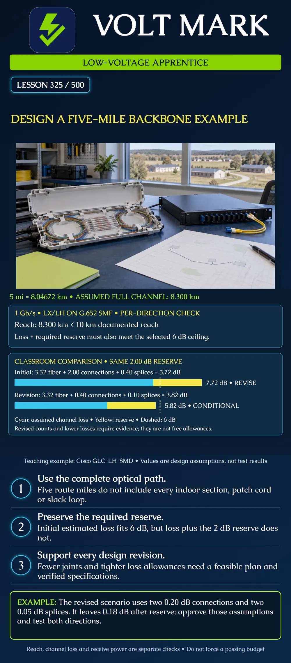
Evaluate a five-mile route, identify a reserve shortfall and develop a conditional revision without hiding the assumptions that make it pass.
This independent classroom scenario requires 1 Gb/s duplex Ethernet. The route is five international miles: 5 × 1.609344 = 8.04672 km. Assume a full 8.300 km optical channel in each direction. The additional 253.28 m represents invented routing, slack and patch-cord contributions, not a standard allowance.
Consider GLC-LH-SMD modules on compatible hosts with G.652 single-mode fiber. Cisco documents 10 km LX/LH reach and a 6 dB SMF channel insertion-loss entry. The table separately gives transmit power from -9.5 to -3 dBm and receive power from -20 to -3 dBm. The manufacturer requires receiver and channel-loss specifications to be satisfied. This exercise uses the published 6 dB ceiling without asserting any shorter-distance exception.
At 1310 nm, assume:
All values are classroom inputs. The reserve is not physical attenuation already installed. A mated connection is counted once, not once per connector half.
Fiber loss: 8.300 × 0.40 = 3.32 dB. Connection loss: 4 × 0.50 = 2.00 dB. Splice loss: 4 × 0.10 = 0.40 dB. Estimated physical loss: 3.32 + 2.00 + 0.40 = 5.72 dB. Including reserve: 5.72 + 2.00 = 7.72 dB.
The length is within the documented reach. The estimated physical loss is below 6 dB, but the plan cannot retain its full required reserve within that ceiling. The shortfall is 7.72 - 6.00 = 1.72 dB. That is a design-reserve failure, not proof that the unbuilt link cannot ever pass traffic.
Suppose the approved physical layout can remove unnecessary cross-connects and intermediate splice points. The proposed revision assumes two mated connections, each with a supported maximum allowance of 0.20 dB, and two splices at 0.05 dB each. The fiber allowance remains unchanged.
Revised estimated loss: 3.32 + (2 × 0.20) + (2 × 0.05) = 3.82 dB. Including the unchanged reserve: 3.82 + 2.00 = 5.82 dB. Remaining space below the ceiling: 6.00 - 5.82 = 0.18 dB.
This is a conditional design candidate. Confirm that the construction plan can achieve those counts and that product specifications, installation methods and acceptance criteria support the tighter allowances. A splicer's estimated loss alone does not substantiate a completed channel. If the assumptions cannot be supported, this revision is not available merely because its arithmetic works.
For the revised physical estimate at minimum transmit power: -9.5 - 3.82 = -13.32 dBm. If the entire reserve becomes additional attenuation: -9.5 - 5.82 = -15.32 dBm. Both are above the stated -20 dBm minimum receive level.
At the other end of the range, the specified maximum launch and maximum receive input are both -3 dBm for this example. Nonnegative passive loss does not raise power above the launch value. Confirm actual equipment and measured levels; different optics can require attenuation. Raw power subtraction does not waive the channel specification.
The final route adds a required splice enclosure containing one additional splice in each working fiber. Under the revised 0.05 dB per-splice assumption, the per-direction total with reserve becomes 5.87 dB. Remaining space becomes 0.13 dB.
Update the inventory and review the available reserve and evidence. Do not keep the old count because the new total still fits. If another design change creates an unsupported assumption, reopen the review.
Confirm service rate, host/software compatibility, fiber and connector interfaces, polarity and environmental suitability. Resolve cable ratings, entrances, pathway permissions and any conductive-component review. Verify the full optical length and inventory. Establish the required insertion-loss, polarity and other project tests, preserve results and obtain the responsible technical review.
If the conditional redesign is not feasible, evaluate another documented optical solution or an approved topology change. Recheck all limits; do not simply buy a stronger transmitter. This lesson does not authorize either procurement or field changes.
Answer: 8.04672 km.
Answer: Its 7.72 dB loss-plus-reserve exceeds the selected 6 dB ceiling.
Answer: Verified specifications, feasible construction and appropriate acceptance evidence.
Answer: 0.18 dB.
Answer: No; they are design-total comparisons.
Mistake: Approving the initial design because its 5.72 dB physical estimate is below 6 dB. Correction: Include the required 2.00 dB reserve: 7.72 dB exceeds the ceiling by 1.72 dB, so the proposed design needs revision.
Mistake: Entering lower connector and splice values solely to make the spreadsheet pass. Correction: Attach specifications and a feasible construction inventory supporting each revised allowance before using the 5.82 dB candidate.
Mistake: Keeping the old splice count after a new enclosure is added. Correction: Record the added splice in each affected path and recalculate the per-direction total, including the unchanged reserve.
Starting with the conditional 5.82 dB total, add two separate splices per direction at 0.05 dB each. Keep the reserve and explain whether this approves construction.
Answer: 5.82 + 0.10 = 5.92 dB, leaving 0.08 dB below 6.00 dB. Only the arithmetic fits; supported allowances, compatibility and the complete design still require review.
Accessed 2026-10-01. Cisco, SFP Modules for Gigabit Ethernet Applications Data Sheet, LX/LH description and optical table: https://www.cisco.com/c/en/us/products/collateral/interfaces-modules/gigabit-ethernet-gbic-sfp-modules/datasheet-c78-366584.html Used for named-family reach, channel-loss entry and power ranges. No exception or host-specific qualification is asserted.
Original scenario, proportional bars and loss assumptions.
Texas journeyman, 15 questions, scored by topic against the 70% mark. No card, and no account needed to start.
Free study material for low-voltage apprentices. This is a national foundation course: requirements differ by state and by local jurisdiction, and a practice that is common in one place is not a rule everywhere. Nothing here is a licence, a certification, or authority to work unsupervised, and completing it does not count as apprenticeship hours or continuing-education credit. Check the codes adopted where you are working, the licensing authority for that work, and your employer's safety programme. VoltMark is not affiliated with, endorsed by, or sponsored by NFPA, OSHA, NICET, BICSI, FOA, or any state or local licensing authority.

Electrician licensing exam prep: practice questions, timed exam simulations, and step-by-step help finding every answer in the NEC.