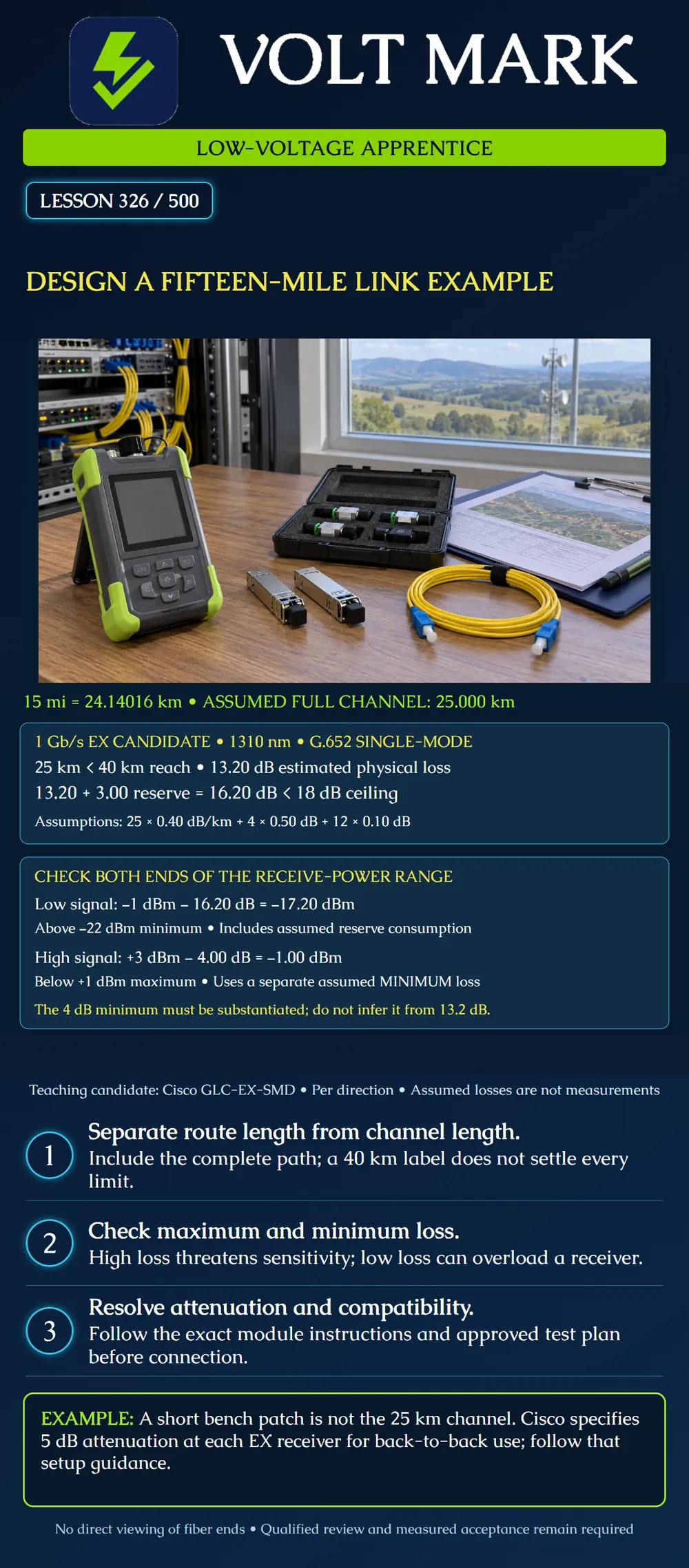
Evaluate a fictional fifteen-mile fiber link using separate reach, maximum-loss and minimum-loss checks.
This classroom link carries 1 Gb/s duplex Ethernet. Fifteen international miles equal 24.14016 km. Assume a full optical channel of 25.000 km per direction after accounting for all routing, slack and patch cords. The extra 859.84 m is an exercise input, not a standard allowance.
Consider a pair of Cisco GLC-EX-SMD modules with compatible hosts and G.652 single-mode fiber. The published EX reach is 40 km, and the channel-loss table lists 18 dB for G.652. Transmit power spans -1 to +3 dBm; receive power spans -22 to +1 dBm. These are separate constraints, not interchangeable ways to approve a link.
Assume, at 1310 nm: 25.000 km fiber at 0.40 dB/km = 10.00 dB. Four mated connections at 0.50 dB = 2.00 dB. Twelve splices at 0.10 dB = 1.20 dB. Estimated maximum physical loss = 13.20 dB. Additional project reserve = 3.00 dB. Design total including reserve = 16.20 dB. Remaining space under the selected 18 dB ceiling = 1.80 dB.
These are assumed upper allowances, not measured results. Confirm the complete inventory and component specifications in a real design. The reserve represents room for additional loss and uncertainty according to the project plan; it is not a physical component.
At minimum transmit power and with the reserve fully consumed: -1 dBm - 16.20 dB = -17.20 dBm. This is 4.80 dB above the stated minimum receive level. Before reserve consumption, the estimate is -1 - 13.20 = -14.20 dBm.
Do not replace the 18 dB channel entry with the larger difference between transmitter and receiver minimum powers. Reach and all applicable channel requirements still apply.
Receiver overload must use the smallest credible channel attenuation, not the upper allowance used above. For this exercise, assume an independently substantiated minimum channel loss of 4.00 dB. That lower bound must have its own evidence; it cannot be inferred from the maximum-loss calculation.
At maximum transmit power: +3 dBm - 4.00 dB = -1.00 dBm. This remains below the +1 dBm maximum receive input.
Pure power arithmetic would require at least 2.00 dB of loss to keep +3 dBm at or below +1 dBm. That boundary is not a recommended attenuator selection or a complete design margin. Use the manufacturer's instructions, tolerances and approved engineering criteria. If the minimum channel loss is unknown, mark the overload check unresolved.
A technician proposes joining the EX modules with a short patch cord to test them before deployment. The installed route's loss cannot be assumed for that setup. Cisco specifies 5 dB attenuation at each receiving port for EX back-to-back connectivity.
Follow the exact vendor setup, suitable attenuator specifications and qualified test procedure. Do not connect the modules through an unreviewed short patch simply because the planned field route is long. A safe field configuration and a bench configuration can have very different attenuation.
Four additional splices enter the approved plan. At the classroom allowance of 0.10 dB each, they add 0.40 dB. The revised total including reserve is 16.60 dB, leaving 1.40 dB below the selected ceiling.
Update the design and records even though the arithmetic still fits. Reassess the complete channel, including minimum-loss assumptions and test boundaries. A revised count is not an instruction to splice or bypass an enclosure without the appropriate authorization.
Confirm actual host ports and software support, exact module models, optical interfaces, operating environment and transmit/receive polarity. Review any required attenuation with its wavelength, tolerance, power handling and location. Check the complete cable route, ratings, entrances, bonding considerations and permissions.
Establish the test plan and acceptance criteria before installation. Retain measured loss results, applicable traces, identifiers and receiver readings. Use approved fiber inspection practices without direct eye viewing. Do not treat a live link indicator or a nominal reach label as full acceptance.
Answer: 24.14016 km.
Answer: 25.000 km per direction.
Answer: 16.20 dB.
Answer: The substantiated minimum channel loss.
Answer: No; each needs separate support.
Answer: No; follow the manufacturer's back-to-back attenuation guidance.
Mistake: Using the 13.20 dB upper-loss estimate to clear the overload check. Correction: Use independently supported minimum loss with maximum launch power; leave overload unresolved when the lower bound is unknown.
Mistake: Applying the long field route's attenuation to a short bench patch. Correction: Check the exact back-to-back instructions and approved test setup before connecting EX optics.
Mistake: Treating a favorable power subtraction as permission to ignore the 18 dB channel entry. Correction: Keep reach, channel attenuation and both receive-power extremes as separate documented checks.
Use the stated +3 dBm maximum launch and +1 dBm maximum receive input. If a separate classroom path has a substantiated minimum loss of 1.00 dB, calculate maximum receive power and compare it with the limit.
Answer: +3 - 1 = +2 dBm, which is 1 dB above the receive limit. Refer the design for correction and recheck both power extremes; the calculation is not an attenuator prescription.
Accessed 2026-10-01. Cisco, SFP Modules for Gigabit Ethernet Applications Data Sheet, EX description and tables 2, 3 and 5: https://www.cisco.com/c/en/us/products/collateral/interfaces-modules/gigabit-ethernet-gbic-sfp-modules/datasheet-c78-366584.html Used for named-family reach, fiber type, power/channel limits and back-to-back attenuation. No shorter-distance exception is asserted.
Original scenario and independently labeled upper/lower loss assumptions.
Texas journeyman, 15 questions, scored by topic against the 70% mark. No card, and no account needed to start.
Free study material for low-voltage apprentices. This is a national foundation course: requirements differ by state and by local jurisdiction, and a practice that is common in one place is not a rule everywhere. Nothing here is a licence, a certification, or authority to work unsupervised, and completing it does not count as apprenticeship hours or continuing-education credit. Check the codes adopted where you are working, the licensing authority for that work, and your employer's safety programme. VoltMark is not affiliated with, endorsed by, or sponsored by NFPA, OSHA, NICET, BICSI, FOA, or any state or local licensing authority.

Electrician licensing exam prep: practice questions, timed exam simulations, and step-by-step help finding every answer in the NEC.