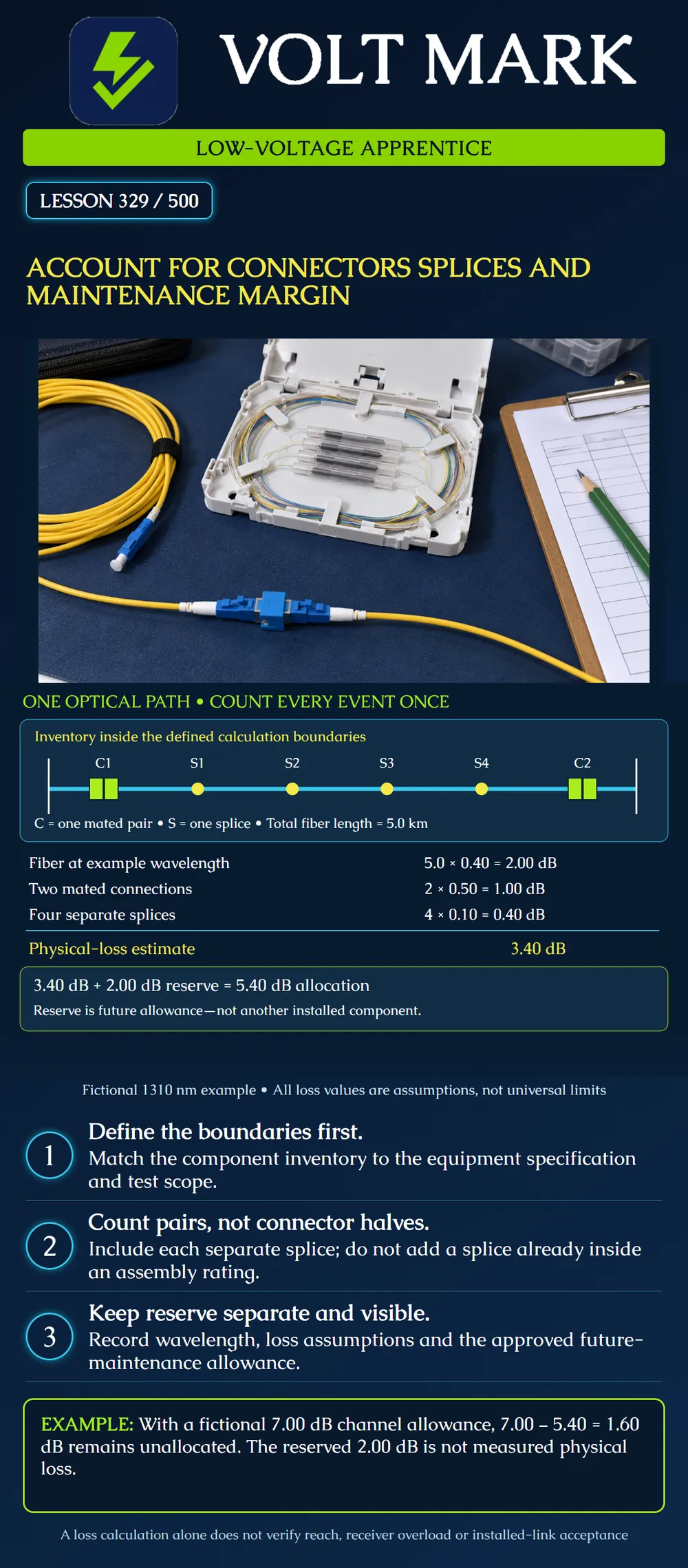
Build a traceable loss inventory for one optical path, distinguish installed-component loss from future allowance, and find duplicate or missing entries. This is a fictional arithmetic exercise, not an approved design or field acceptance criterion.
A loss estimate adds fiber attenuation, mated-connection loss, splice loss and any other passive-device loss inside a defined boundary. Use the operating wavelength and appropriate component specifications. A connection is the joined pair: if a value is specified per mated pair, do not charge it twice for its two halves. The calculation and test reference method must describe compatible boundaries. Sources 1 and 2 support these accounting principles.
Start with a marked drawing. Name the path, its endpoints and the wavelength, then list each event in signal order. Record the full fiber length within that scope, including relevant slack and patch leads. Reconcile the endpoints with the equipment manufacturer's definition; do not silently omit or add a connection at an optical reference plane.
Keep the basis of every allowance visible. A typical value, a guaranteed maximum and a measured result are different records. For an assembly whose loss rating already includes its internal splice, adding that splice again would duplicate the same loss. Conversely, a separate pigtail splice needs its own entry when it is outside the rated connection value.
Maintenance reserve is a deliberate allowance for future changes or restoration. It is not a component that a meter can find. FOA discusses repair splices consuming available margin. The amount retained, how it may be used and the required re-evaluation belong in the project design. No fixed nationwide reserve is asserted here.
Assume this single-mode example operates at 1310 nm:
All these component values are exercise assumptions. They are not quoted product ratings, universal TIA limits or a recommendation to accept these values on a real project.
For arithmetic only, assume the selected system permits a 7.00 dB channel attenuation allowance at these same boundaries after applicable system restrictions have been addressed. The remaining unallocated allowance is 7.00 − 5.40 = 1.60 dB. Do not label all 3.60 dB between 3.40 and 7.00 as freely available: 2.00 dB has already been reserved.
A fictional repair adds 0.10 km of fiber and two new splices under the same assumptions: Additional fiber = 0.10 × 0.40 = 0.04 dB. Additional splices = 2 × 0.10 = 0.20 dB. Additional estimated physical loss = 0.24 dB. Revised physical estimate = 3.40 + 0.24 = 3.64 dB.
If the authorized design consumes 0.24 dB from the existing reserve, the remaining reserve becomes 1.76 dB and combined allocation remains 5.40 dB. If the project instead requires restoring the full 2.00 dB reserve, combined allocation becomes 5.64 dB and unallocated allowance becomes 1.36 dB. Record which policy applies; an apprentice must not choose it silently. Actual repair testing and updated records are still required.
A trainee enters four connector halves at 0.50 dB each. That makes the connection subtotal 2.00 dB, incorrectly increasing the physical estimate to 4.40 dB. Correct the unit to “mated pair” and the quantity to two. Another trainee uses a hypothetical 0.60 dB assembly value that includes a 0.10 dB internal splice, then adds that same internal splice separately. That would incorrectly produce 0.70 dB for the assembly. Check the manufacturer's stated scope before deciding whether a splice is separate.
Record path ID; drawing revision; direction; fiber type; wavelength; calculation boundaries; fiber length and its evidence; each connection ID; each separate splice ID; any splitter, filter or attenuator; rated-loss basis; physical subtotal; reserve policy; applicable system allowance; unallocated remainder; test method and uncertainty treatment; review owner.
Mistake: Counting four connector halves as four mated connections. Correction: Count the two joined pairs once each at the stated per-pair allowance; reconcile the calculation and test boundaries.
Mistake: Adding an internal splice already covered by an assembly's loss rating. Correction: Read the rating scope and enter only losses outside it as separate events.
Mistake: Spending maintenance reserve while still reporting the original reserve available. Correction: Record whether the repair consumes reserve or the design must retain its full amount, then recalculate the remaining allocation.
Texas journeyman, 15 questions, scored by topic against the 70% mark. No card, and no account needed to start.
Free study material for low-voltage apprentices. This is a national foundation course: requirements differ by state and by local jurisdiction, and a practice that is common in one place is not a rule everywhere. Nothing here is a licence, a certification, or authority to work unsupervised, and completing it does not count as apprenticeship hours or continuing-education credit. Check the codes adopted where you are working, the licensing authority for that work, and your employer's safety programme. VoltMark is not affiliated with, endorsed by, or sponsored by NFPA, OSHA, NICET, BICSI, FOA, or any state or local licensing authority.

Electrician licensing exam prep: practice questions, timed exam simulations, and step-by-step help finding every answer in the NEC.