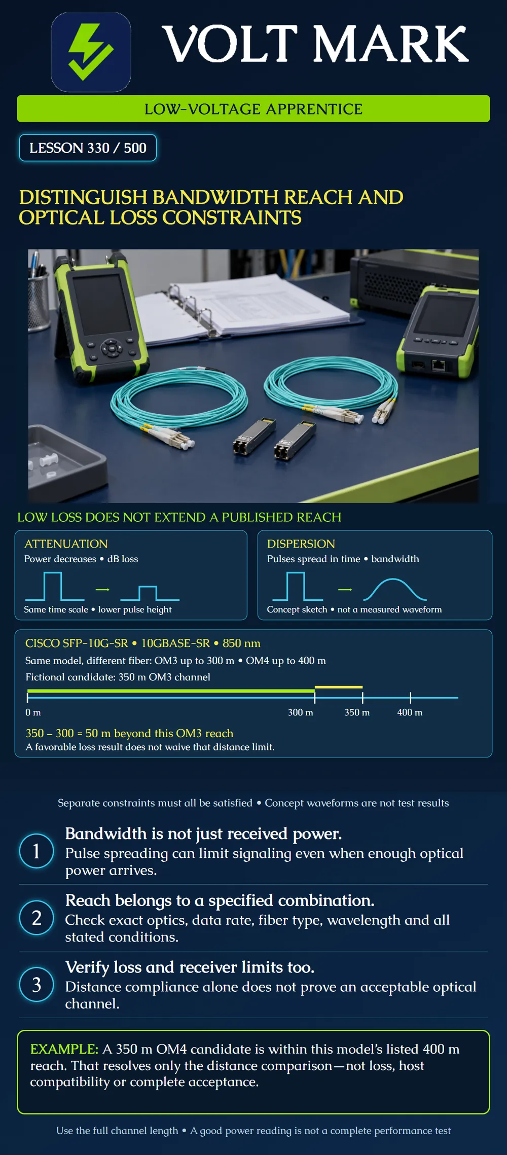
Separate three questions: can the chosen optical system carry the required signal, is the channel within its supported reach, and does its optical loss and received-power range meet the applicable limits? Explain why passing one comparison cannot substitute for the others.
Attenuation reduces optical power. Dispersion spreads pulses over time and can make adjacent symbols harder to distinguish. For multimode fiber, modal behavior and launch conditions affect bandwidth. Modal-bandwidth units such as MHz·km are not attenuation units such as dB/km, nor are they Ethernet bit rates. Corning AEN081 explains these distinctions and cautions against assuming a simple inverse relationship between distance and bandwidth. We use its stable physics, not its historical standards references as present-day requirements.
The two pulse sketches isolate concepts. The left shows a smaller pulse with unchanged illustrative duration; the right shows spreading. Actual links may exhibit both at once. Neither drawing is a measured waveform, a calibrated eye diagram, or a prediction for the named product. Pulse height and width here teach different failure mechanisms.
Cisco lists SFP-10G-SR as a 10GBASE-SR optical module using 850 nm multimode fiber. Its stated reach is up to 300 m with OM3 and up to 400 m with OM4. These are specifications for this named combination; do not attach them to every 10G optic, every multimode cable or every protocol. Other required specifications and host support still apply.
An inventory describes a 350 m full OM3 channel intended for that model. The distance comparison is: 350 m actual candidate length − 300 m listed reach = 50 m beyond the specified reach.
Suppose someone reports a favorable insertion-loss result. That evidence does not change 350 m into 300 m, prove the required bandwidth behavior or grant a reach exception. Record the distance conflict and refer the design for correction. Do not increase transmit power or substitute an attenuator as an assumed cure for a dispersion or reach problem.
The poster uses a proportional distance axis: the OM3 reach ends at 300 m, with a separate yellow segment extending another 50 m to the candidate length. The 400 m tick is a scale reference; it does not make this OM3 candidate an OM4 channel.
Now consider a separately documented 350 m OM4 channel using the same specified optic. Its length is 50 m below the published 400 m reach. The distance comparison is favorable, but the fiber identity, loss, receive-power limits, polarity, compatible endpoints and relevant operating conditions still require evidence.
Changing a worksheet label from OM3 to OM4 is not a physical upgrade. Existing cable and patch leads need traceable identification. A few new OM4 patch cords do not establish that the rest of an unknown channel has OM4 performance.
To illustrate a separate loss comparison, assume a fictional system has an approved 2.00 dB channel-loss ceiling for the defined scope. This number is invented for arithmetic and is NOT a Cisco SFP-10G-SR specification. A 150 m channel in that fictional system has a measured 2.30 dB insertion loss: 2.30 − 2.00 = 0.30 dB above the assumed ceiling.
Being short does not erase the excess loss. Before interpreting any real result, confirm the applicable test method, wavelength, reference, calibration and measurement uncertainty. This exercise deliberately does not supply a real acceptance rule or tell the apprentice to modify a live system.
For a training worksheet, use one row each for:
Mark each row “supported,” “conflict,” or “missing evidence,” and identify the supporting record. One supported row cannot automatically close the others. This is an evidence exercise, not a substitute for a project's commissioning plan.
A route map lists 280 m between rooms. Installed slack and patching add 35 m within the channel scope. What length belongs in the comparison?
Answer: 315 m, not 280 m. For the named OM3 example, that is 15 m beyond 300 m. Confirm the lengths rather than assuming this addition applies to every project.
Mistake: Accepting the 350 m OM3 candidate because measured loss is low. Correction: Compare its complete length with the named optic's OM3 reach independently of the loss result; refer the excess distance for redesign.
Mistake: Treating MHz·km as an attenuation figure. Correction: Keep bandwidth and pulse-spreading evidence separate from dB/km attenuation and dB channel loss.
Mistake: Relabeling the whole channel OM4 after replacing only patch leads. Correction: Verify the installed cable and every relevant channel segment before using the OM4 reach comparison.
Sources checked October 1, 2026. Scenarios and waveforms are original teaching examples.
Texas journeyman, 15 questions, scored by topic against the 70% mark. No card, and no account needed to start.
Free study material for low-voltage apprentices. This is a national foundation course: requirements differ by state and by local jurisdiction, and a practice that is common in one place is not a rule everywhere. Nothing here is a licence, a certification, or authority to work unsupervised, and completing it does not count as apprenticeship hours or continuing-education credit. Check the codes adopted where you are working, the licensing authority for that work, and your employer's safety programme. VoltMark is not affiliated with, endorsed by, or sponsored by NFPA, OSHA, NICET, BICSI, FOA, or any state or local licensing authority.

Electrician licensing exam prep: practice questions, timed exam simulations, and step-by-step help finding every answer in the NEC.