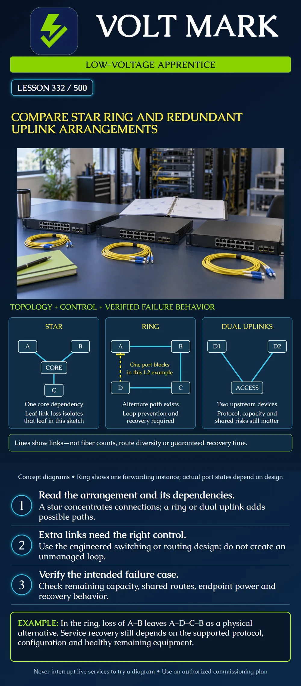
Compare the physical relationships of a star, a ring and redundant uplinks. Identify a failure each arrangement can expose, and separate an available physical path from a verified recovery mechanism.
A topology drawing shows relationships, not a complete reliability claim. In a star, leaf nodes connect to a central node. A ring provides a cycle of links. Dual uplinks give a downstream device two upstream connections. Each may be implemented in different ways; the three sketches are deliberately limited examples, not competing universal prescriptions.
Cisco's spanning-tree guidance explains how a redundant Layer 2 topology can operate without a forwarding loop. A standby path can become active after the topology changes. Actual port roles depend on the selected protocol, instance and configuration. A ring-shaped cable drawing alone does not provide this control.
Cisco's campus design guidance distinguishes switching, routing and multichassis arrangements. Do not assume that two connections to independent upstream devices can simply be placed in one ordinary link-aggregation group. The supported equipment architecture and configuration must provide that behavior. This lesson supplies no switch commands or live-network change instructions.
STAR: Leaf A, leaf B and leaf C each connect to the one illustrated CORE. Only these links are assumed. A failure of the C-to-core link isolates C from the other drawn nodes. A core failure affects all three leaves' connectivity through that core. This is a single-core example, not a claim that every star design lacks redundancy.
RING: A connects to B, B to C, C to D and D to A. Yellow marks an example port near A that is blocked for the illustrated Layer 2 forwarding instance. The dashed A–D link is physically present; it is not a broken cable. A different instance or protocol may have different states. The concept is controlled forwarding, not an instruction to block a particular port.
DUAL UPLINKS: ACCESS has one connection to distribution device D1 and another to D2. The drawing omits upstream services and interconnections so it cannot prove end-to-end resilience. It also retains ACCESS as a common device. A failure there is not cured merely by having two uplinks.
Assume all four nodes remain healthy but the A–B link fails. Follow the remaining physical route from A to B: A → D → C → B. There are three remaining links on that route. For traffic to use it, the selected control mechanism must recognize the change and permit the necessary forwarding. Do not promise uninterrupted service or a universal recovery time.
Now assume both A–B and C–D fail. The remaining links form two groups: A with D, and B with C. No path between the groups exists in the sketch. Software cannot use a physical connection that is not present. If a node fails instead of a link, services attached to that failed node also need separate consideration.
Imagine ACCESS needs to carry a combined 7 Gb/s of required traffic during a planned single-uplink outage. For arithmetic only, assume each surviving uplink has an assessed usable capacity of 5 Gb/s for that traffic: 7 − 5 = 2 Gb/s shortfall. Two uplinks existing before the outage do not make one surviving uplink large enough. These are fictional usable-capacity assumptions, not line-rate promises. A real assessment must include traffic direction, overhead, congestion and the service requirement.
If D1 fails, recovery also requires D2 to reach the needed services and the network to select that path correctly. If both uplink cables pass through the same damaged handhole, both can be lost. Refer back to lesson 331 for the physical-route assessment.
For each sketch, record:
A good answer includes “unknown” where evidence is missing. It does not turn an unlabeled line into a pair of fibers, an independent underground corridor or a configured backup route.
Mistake: Reading the dashed ring link as a missing or broken cable. Correction: Use the legend: the link exists, while an example port is blocked for the shown forwarding instance.
Mistake: Assuming two uplinks can carry the original load after either fails. Correction: Compare required traffic with the surviving usable capacity; the 7 Gb/s demand exceeds the assumed 5 Gb/s survivor by 2 Gb/s.
Mistake: Calling ACCESS redundant because it reaches D1 and D2. Correction: List ACCESS itself, its power and upstream dependencies before claiming device or end-to-end resilience.
Cisco, STP Configuration Guide, Spanning Tree Protocol, updated July 17, 2026: https://www.cisco.com/c/en/us/td/docs/switches/lan/c9000/lyr2-fwd/stp/stp-configuration-guide/m-stp.html Used for loop prevention, standby paths and topology-change behavior. No universal convergence time or configuration prescription adopted.
Cisco, Campus LAN and Wireless LAN Solution Design Guide: https://www.cisco.com/c/en/us/td/docs/solutions/CVD/Campus/cisco-campus-lan-wlan-design-guide.html Used for distinct uplink and distribution architectures. Historical model recommendations are not treated as a current buying list.
Primary sources accessed October 1, 2026. Diagrams, failure cases and capacity numbers are original classroom exercises.
Texas journeyman, 15 questions, scored by topic against the 70% mark. No card, and no account needed to start.
Free study material for low-voltage apprentices. This is a national foundation course: requirements differ by state and by local jurisdiction, and a practice that is common in one place is not a rule everywhere. Nothing here is a licence, a certification, or authority to work unsupervised, and completing it does not count as apprenticeship hours or continuing-education credit. Check the codes adopted where you are working, the licensing authority for that work, and your employer's safety programme. VoltMark is not affiliated with, endorsed by, or sponsored by NFPA, OSHA, NICET, BICSI, FOA, or any state or local licensing authority.

Electrician licensing exam prep: practice questions, timed exam simulations, and step-by-step help finding every answer in the NEC.