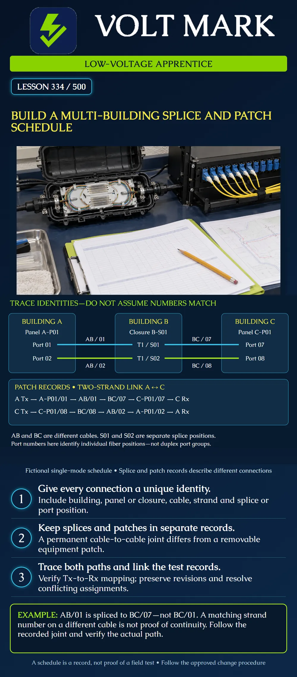
Build consistent splice, termination and patch records for one two-strand link crossing three buildings. Trace each transmitter to the far receiver using explicit identities.
FOA's installation guidance calls for documentation of each fiber's path, intermediate connections, connector types and associated test evidence. Its termination guidance distinguishes permanent splice joints from connector-based connections that can be changed by patching. Those distinctions support separate records linked by common identifiers.
A strand number is meaningful only within its cable identification scheme. “Fiber 01” alone is insufficient when several cables reach the same room. Panel positions also need a panel and building identifier. Document which numbering convention is used, especially where a panel label denotes a duplex group rather than an individual fiber position.
This fictional single-mode link runs from Building A through Building B to Building C: Cable AB connects A-P01 at Building A to closure B-S01 at Building B. Cable BC connects B-S01 to C-P01 at Building C. At Building B, tray T1 holds two separate fusion splices. The simplified example assumes directly connectorized cable ends at the endpoint panels; it contains no unrecorded endpoint pigtail splices. A real pigtail installation would require those additional joints in its termination records. All component ratings and installation requirements remain a separate design matter.
Every port number in this lesson is an individual fiber position. AB/01 and BC/07 mean cable AB strand 01 and cable BC strand 07. The slash is a record separator, not a mathematical operation.
A-P01 / individual position 01 / rear cable AB / strand 01. A-P01 / individual position 02 / rear cable AB / strand 02. C-P01 / individual position 07 / rear cable BC / strand 07. C-P01 / individual position 08 / rear cable BC / strand 08. For the classroom inventory, each panel interface is LC/UPC with matching single-mode patch leads. This is an example choice, not a requirement for every fiber network.
Closure B-S01, tray T1, position S01: Cable AB strand 01 joined to cable BC strand 07. Closure B-S01, tray T1, position S02: Cable AB strand 02 joined to cable BC strand 08.
These are two one-to-one joints. There is no splitter, no branch to local Building B equipment and no implied connection between the two joints. Building B is a through-splice location for this service.
Patch PA-T: equipment A optical Tx to A-P01 position 01. Patch PA-R: equipment A optical Rx to A-P01 position 02. Patch PC-R: C-P01 position 07 to equipment C optical Rx. Patch PC-T: C-P01 position 08 to equipment C optical Tx.
These IDs identify individual optical patch paths. Physical patch cords may have duplex housings; record each leg and its actual equipment-port mapping. Do not infer polarity from how a connector appears when viewed from the front or rear.
Forward signal: A Tx → PA-T → A-P01/01 → AB/01 → B-S01/T1/S01 → BC/07 → C-P01/07 → PC-R → C Rx. Return signal: C Tx → PC-T → C-P01/08 → BC/08 → B-S01/T1/S02 → AB/02 → A-P01/02 → PA-R → A Rx.
The poster shortens these paths to fit, while the records above retain the joint and patch identifiers. Each signal uses one strand from each cable segment, joined at B. Across the two cable segments, four strand-segment assignments form two continuous optical paths for one duplex service.
Read the forward trace in reverse and confirm that the same endpoints and joints are found. Then independently trace the return signal. Reversing the direction used to read a record does not change which equipment connector transmits.
Check that no strand in this point-to-point exercise is assigned to two conflicting joints. Confirm the physical labels against the current authorized record and associate tests with the exact endpoints and path revision. A completed worksheet does not prove continuity, loss or acceptable network operation.
A draft patch row connects C-P01/07 to C Tx, while A-P01/01 connects to A Tx. The documented cable path would join Tx to Tx. Flag the conflict; reconcile the design and approved equipment mapping before anyone patches a live system. The correct classroom schedule connects C-P01/07 to C Rx.
If a later authorized change moves the BC side of S01 from strand 07 to strand 09, updating the splice row alone is insufficient. Reconcile the C termination, patch row, allocation register, labels and test references. Do not silently reuse the old test result for the revised path.
Mistake: Joining equal strand numbers across cables without consulting the splice schedule. Correction: Follow the documented cable-specific identities: AB/01 joins BC/07 at B-S01/T1/S01 in this example.
Mistake: Reading a duplex housing or panel orientation as proof of polarity. Correction: Trace each equipment transmitter through patch, panel and splice records to the far receiver.
Mistake: Changing BC/07 to BC/09 only in the splice row. Correction: Reconcile termination, patch, allocation, labels and test references to the revised end-to-end path before acceptance.
The Fiber Optic Association, Outside Plant Fiber Optic Cable Plant Installation: https://www.thefoa.org/tech/ref/OSP/install.html Used for path, connection and test documentation principles. Installation depths, construction procedures and historical code references on the broader page are not adopted here.
The Fiber Optic Association, Outside Plant Fiber Optic Splicing and Termination: https://www.thefoa.org/tech/ref/OSP/term.html Used for the distinction between splices and connector-based patching.
Primary sources checked October 1, 2026. All identifiers, schedules and traces are original classroom examples.
Texas journeyman, 15 questions, scored by topic against the 70% mark. No card, and no account needed to start.
Free study material for low-voltage apprentices. This is a national foundation course: requirements differ by state and by local jurisdiction, and a practice that is common in one place is not a rule everywhere. Nothing here is a licence, a certification, or authority to work unsupervised, and completing it does not count as apprenticeship hours or continuing-education credit. Check the codes adopted where you are working, the licensing authority for that work, and your employer's safety programme. VoltMark is not affiliated with, endorsed by, or sponsored by NFPA, OSHA, NICET, BICSI, FOA, or any state or local licensing authority.

Electrician licensing exam prep: practice questions, timed exam simulations, and step-by-step help finding every answer in the NEC.