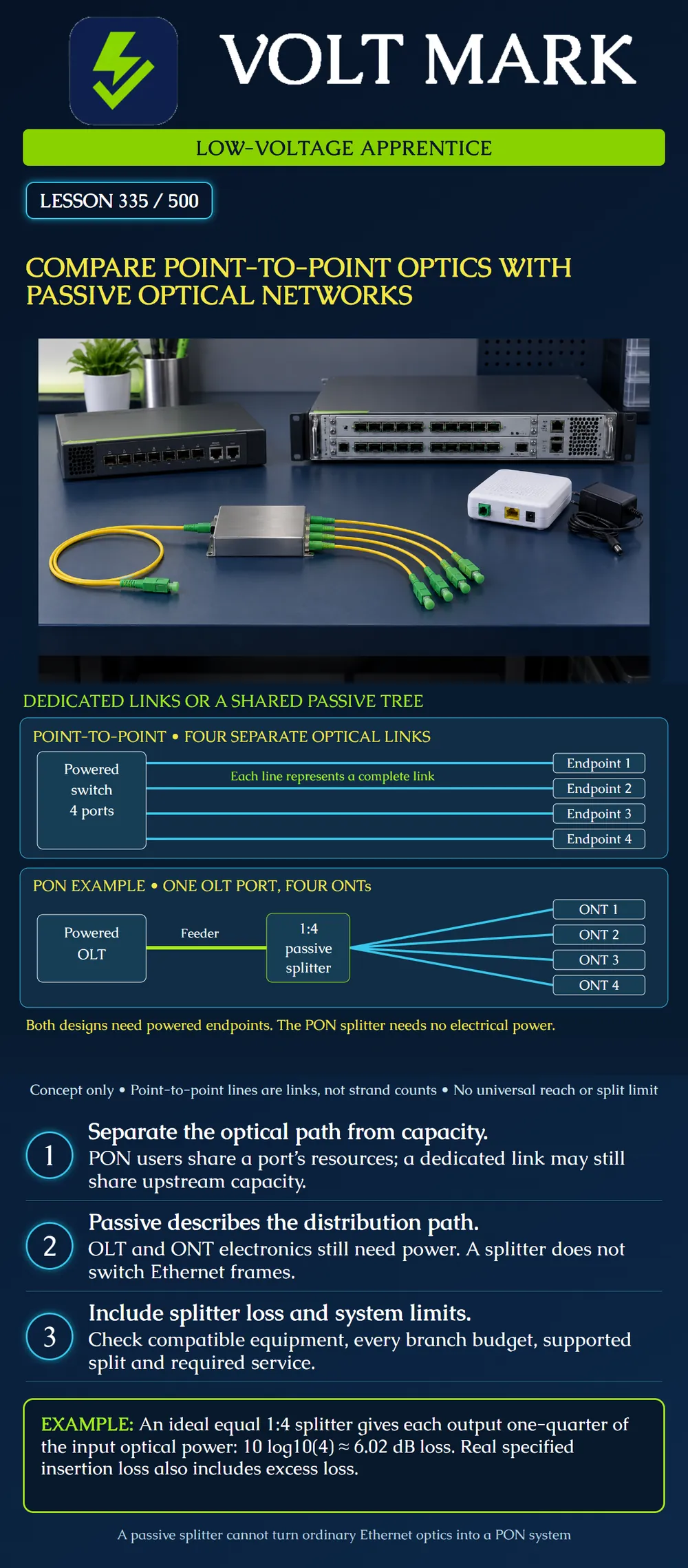
Recognize a dedicated point-to-point optical link and a splitter-based passive optical network. Compare the path, shared resources, power dependencies and loss considerations without assuming that one design suits every project.
A point-to-point arrangement connects two optical endpoints. In the poster's four-link example, a central powered switch has a separate optical port and link for each remote endpoint. A line represents a complete link; its actual strand count depends on the optical design. Dedicated access links do not guarantee dedicated capacity throughout the upstream network.
In the illustrated PON, one optical line terminal (OLT) port connects through a feeder to a passive splitter and four optical network terminals (ONTs). The splitter distributes downstream light and combines upstream light. The PON equipment and protocol manage communication; the splitter is not an Ethernet switch. The OLT and ONTs require electrical power even though the intervening splitter does not.
FOA's architecture guidance supports these basic relationships. Its broader historical speed, reach and split-ratio tables are not adopted as universal limits in this lesson.
The upper drawing contains four separate lines between the switch and endpoints 1–4. They do not join in the middle. The label “4 ports” refers to this example's four central optical interfaces.
The lower drawing contains one feeder to a 1:4 splitter and four outgoing branches. The triangle-like spread of lines is a schematic fan-out, not a splice joining four bare fibers together. It represents a manufactured optical splitter. The four ONTs are active equipment even though their boxes are small. No building distances, cable routes, redundancy or split-ratio approval are implied.
For these specific four-endpoint drawings: Point-to-point: four central optical link ports and four remote optical endpoints. PON: one OLT PON port, one 1:4 splitter and four ONTs. This comparison is about the drawn optical interfaces, not a complete bill of materials. Chassis, uplinks, patch panels, connectors, power supplies, software and spare capacity still need design decisions.
Do not convert “four point-to-point links” into a fixed fiber count without knowing whether the chosen links use two strands, a compatible single-fiber bidirectional arrangement or another architecture.
For an ideal equal 1:4 split, each output receives one-quarter of the input power: Output/input = 1/4 = 0.25. Ideal division loss = 10 log10(4) = about 6.02 dB.
Assume a fictional splitter has a specified insertion-loss allowance of 7.20 dB at the required wavelength and test boundaries. Use that 7.20 dB allowance in the applicable budget; do not add another 6.02 dB for the same split. The insertion-loss specification already includes the power division. Confirm whether any connectors are included before adding them separately.
If a classroom branch has 2.00 dB of other physical loss outside those boundaries, its example total is 7.20 + 2.00 = 9.20 dB. This does not establish a compliant PON: equipment loss windows, wavelength, reach, reserve and other requirements remain unspecified. The 7.20 and 2.00 values are invented exercise assumptions.
Dividing optical power by four does not mean every subscriber permanently receives exactly one-quarter of a service's data rate. Resource allocation, overhead, provisioning and concurrent demand affect the result. The shared PON port and its upstream connection must support the required service.
For a fictional planning exercise, four sites each require 300 Mb/s simultaneously in the same direction. Their aggregate demand is 4 × 300 = 1,200 Mb/s. If the assessed usable shared capacity for that traffic were 1,000 Mb/s, the shortfall would be 200 Mb/s. These numbers are not a GPON or XGS-PON specification. A four-port point-to-point switch could also encounter a shared-uplink bottleneck.
In the shown PON, a feeder failure can affect all four ONTs; an individual branch failure can affect its ONT. In the point-to-point example, a separate link failure affects that drawn endpoint, but failure of the common switch can affect all four. Both designs can also share physical cable routes or power dependencies that the drawing does not reveal.
Record service and demand; exact optical architecture; fiber and strand count; compatible equipment; central and remote power arrangements; each optical path and splitter; wavelength-specific loss limits; complete length; shared failure points; test requirements; and expansion assumptions. Keep unknowns visible. Do not connect a splitter to ordinary Ethernet optics and expect PON functions to appear.
Mistake: Treating a passive splitter as a switch that powers or schedules endpoints. Correction: Record the OLT and ONTs as powered equipment and identify their control and supply arrangements separately from optical splitting.
Mistake: Adding ideal 1:4 division loss to a complete splitter insertion-loss allowance. Correction: Use the specified path insertion loss once and add only components outside its stated boundaries.
Mistake: Assuming dedicated access links eliminate shared capacity limits. Correction: Check the common switch or PON uplink and simultaneous demand; the four fictional 300 Mb/s demands total 1,200 Mb/s.
The Fiber Optic Association, Fiber To The Home PON Types: https://www.thefoa.org/tech/ref/appln/FTTH-PON.html Used for OLT/splitter/ONT architecture and shared feeder principles. The Fiber Optic Association, Fiber To The Home Network Design: https://www.thefoa.org/tech/ref/appln/FTTH-design.html Used for point-to-point versus PON design distinctions. The Fiber Optic Association, Testing Fiber Optic Couplers, Splitters Or Other Passive Devices: https://www.thefoa.org/tech/ref/testing/test/couplers.html Used for splitting, insertion loss and excess-loss concepts.
Checked October 1, 2026. Historical market-share, cost-saving, security, maximum-split and reach claims are not adopted. Diagrams and numerical cases are original teaching examples.
Texas journeyman, 15 questions, scored by topic against the 70% mark. No card, and no account needed to start.
Free study material for low-voltage apprentices. This is a national foundation course: requirements differ by state and by local jurisdiction, and a practice that is common in one place is not a rule everywhere. Nothing here is a licence, a certification, or authority to work unsupervised, and completing it does not count as apprenticeship hours or continuing-education credit. Check the codes adopted where you are working, the licensing authority for that work, and your employer's safety programme. VoltMark is not affiliated with, endorsed by, or sponsored by NFPA, OSHA, NICET, BICSI, FOA, or any state or local licensing authority.

Electrician licensing exam prep: practice questions, timed exam simulations, and step-by-step help finding every answer in the NEC.