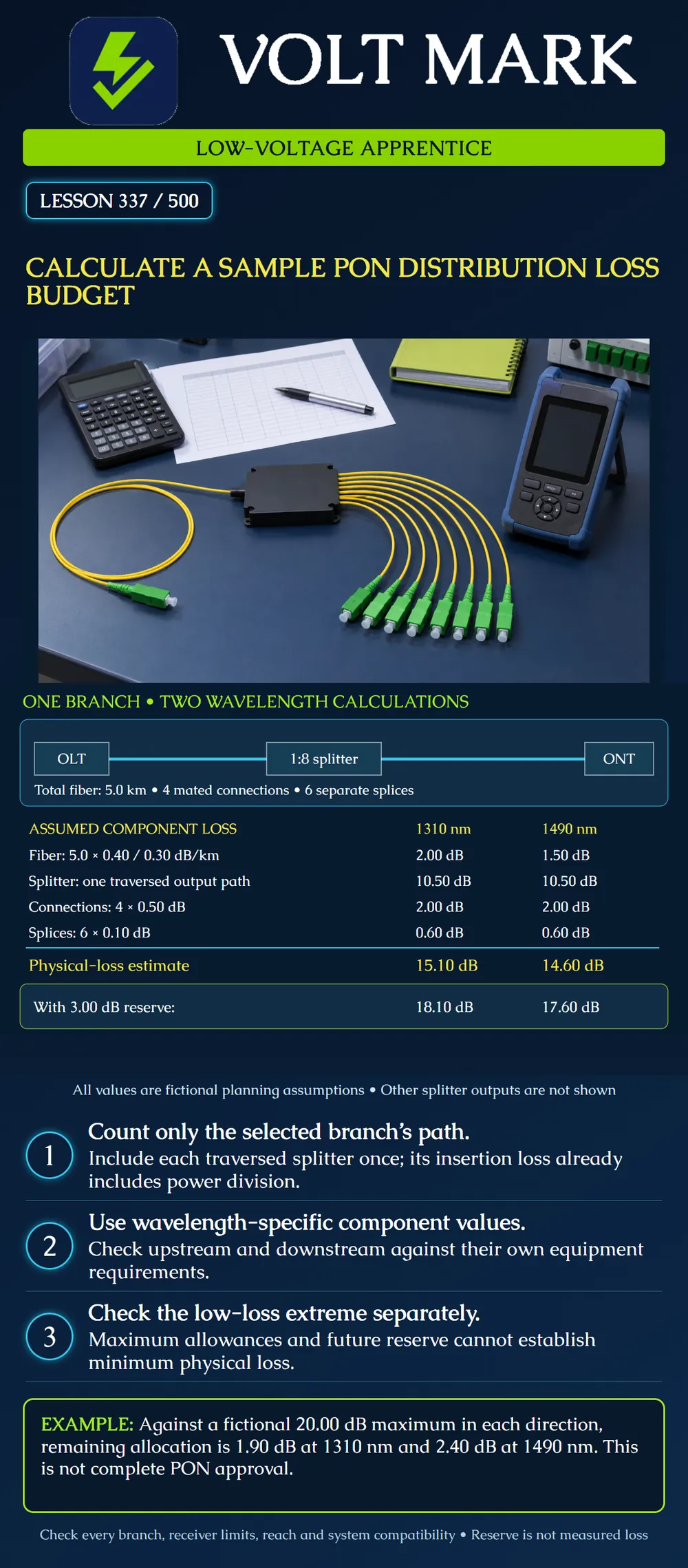
Calculate a fictional PON branch loss estimate at two wavelengths, add an explicit reserve and explain why minimum-loss checks remain separate.
FOA describes optical-loss estimates as sums of fiber, connections, splices and other passive components at the relevant wavelength. Its PON testing guidance includes the splitter and the connections on the selected end-to-end path. The equipment's permitted loss range and the predicted cable-plant loss are different records. Matching calculation boundaries and test boundaries matters.
This lesson uses invented allowances to practice accounting. None is a product rating, universal code value or acceptance limit. The sample wavelengths represent a GPON-style upstream/downstream exercise; other PON systems may use different wavelengths and specifications.
Branch P-01 runs from one OLT optical reference plane, through one 1:8 splitter output path, to one ONT optical reference plane. Total fiber length within the calculation boundary is 5.0 km, including the relevant feeder, branch and leads. There are four mated connections and six separate splices in that path. The fictional splitter allowance is 10.50 dB at each wavelength and excludes the separately listed connection and splice losses. Its own optical power division is already included. There are no other passive devices in this exercise.
Only one of the splitter's eight outputs is traversed by this branch. Do not add the insertion loss of all eight outputs in series. Other branches need their own path inventory and calculation.
Fiber: 5.0 km × 0.40 dB/km = 2.00 dB. Splitter output path: 10.50 dB. Mated connections: 4 × 0.50 dB = 2.00 dB. Separate splices: 6 × 0.10 dB = 0.60 dB. Physical-loss estimate: 2.00 + 10.50 + 2.00 + 0.60 = 15.10 dB. Maintenance reserve: 3.00 dB. Combined design allocation: 18.10 dB.
Fiber: 5.0 km × 0.30 dB/km = 1.50 dB. Splitter output path: 10.50 dB. Mated connections: 2.00 dB. Separate splices: 0.60 dB. Physical-loss estimate: 1.50 + 10.50 + 2.00 + 0.60 = 14.60 dB. Maintenance reserve: 3.00 dB. Combined design allocation: 17.60 dB.
The 0.50 dB difference arises solely from the assumed fiber coefficients. Real splitter and other component specifications may also vary with wavelength, output port and conditions.
Assume, only for this arithmetic exercise, that the selected system allows 20.00 dB maximum path loss in each direction at the same boundaries after applicable system restrictions are addressed. 1310 nm unallocated remainder: 20.00 − 18.10 = 1.90 dB. 1490 nm unallocated remainder: 20.00 − 17.60 = 2.40 dB.
Both comparisons are favorable within those assumptions. They do not establish the actual receiver-power window, distance capability, permitted split ratio, differential path limits, protocol compatibility or installation quality. The 20.00 dB number is not identified as a GPON optical-class limit.
The component allowances above describe an upper-loss planning case. They do not prove that the physical loss can never be lower. The 3.00 dB reserve is future allowance, not attenuation physically present today.
For a separate fictional check, assume a system requires at least 12.00 dB physical loss at a particular wavelength. Independent component evidence establishes a lower bound of 11.20 dB for that case. It falls short by 0.80 dB. Adding a paper reserve does not resolve the issue. Any design correction must be selected and checked against both high-power and weak-signal limits; this example does not prescribe an attenuator.
In a real design, check the actual OLT and ONT transmitter and receiver limits, applicable path-loss windows and operating conditions. Do not infer a lower bound by subtracting an arbitrary margin from an upper bound.
A later revision adds 0.5 km of fiber and one separate splice, retaining the same assumed coefficients: 1310 nm additional loss = 0.5 × 0.40 + 0.10 = 0.30 dB. 1490 nm additional loss = 0.5 × 0.30 + 0.10 = 0.25 dB. With the full 3.00 dB reserve retained, revised allocations are 18.40 and 17.85 dB. Remainders against the fictional 20.00 dB ceiling become 1.60 and 2.15 dB. Update the inventory and review rather than silently consuming a reserve.
Record branch ID; endpoints and reference planes; wavelength and direction; full fiber length; each splitter path and rating scope; mated connections; separate splices; other components; physical subtotal; reserve; equipment limits; lower-bound evidence; test method and uncertainty; revision and reviewer.
Quiz: Do you multiply splitter insertion loss by eight for one traversed output? No. Add ideal splitting loss again to a complete insertion-loss allowance? No. Is a reserve measured loss? No. Can one branch calculation approve the whole tree? No. Are all wavelengths assumed to have identical attenuation? No.
Mistake: Adding the 1:8 splitter's loss eight times for branch P-01. Correction: Follow the one traversed output path and include its insertion-loss allowance once.
Mistake: Using the 3 dB reserve to satisfy a minimum physical-loss requirement. Correction: Keep reserve outside present physical attenuation; compare the independently supported lower bound with the minimum-loss criterion.
Mistake: Copying the 1310 nm result into the 1490 nm row. Correction: Recalculate each wavelength using its own component allowances, including any wavelength-dependent change.
Answer: Other branches have their own lengths, components and endpoint conditions; their records must be checked separately.
Answer: It is 0.80 dB too low, and a future paper reserve does not add attenuation today.
Answer: 18.40 dB at 1310 nm and 17.85 dB at 1490 nm, leaving 1.60 and 2.15 dB against the fictional 20.00 dB ceiling.
The Fiber Optic Association, Calculating Fiber Optic Loss Budgets: https://thefoa.org/tech/lossbudg.htm The Fiber Optic Association, Testing Fiber To The Home: https://www.thefoa.org/tech/ref/appln/FTTH-test.html Checked October 1, 2026. Used for accounting, boundary and minimum/maximum-loss distinctions. Historical component tables and generic limits are not adopted. All numerical cases are original assumptions.
Texas journeyman, 15 questions, scored by topic against the 70% mark. No card, and no account needed to start.
Free study material for low-voltage apprentices. This is a national foundation course: requirements differ by state and by local jurisdiction, and a practice that is common in one place is not a rule everywhere. Nothing here is a licence, a certification, or authority to work unsupervised, and completing it does not count as apprenticeship hours or continuing-education credit. Check the codes adopted where you are working, the licensing authority for that work, and your employer's safety programme. VoltMark is not affiliated with, endorsed by, or sponsored by NFPA, OSHA, NICET, BICSI, FOA, or any state or local licensing authority.

Electrician licensing exam prep: practice questions, timed exam simulations, and step-by-step help finding every answer in the NEC.