Trace a wavelength channel through multiplexing components and identify the evidence needed to establish optical compatibility.
Wavelength-division multiplexing (WDM) carries multiple optical signals on a common fiber using different wavelengths. A multiplexer combines channels; a demultiplexer separates them by wavelength. A passive filter does not change a transmitter's wavelength or translate its data protocol. This differs from an ordinary power splitter that distributes optical power among outputs without providing the same channel-selection function.
The Cisco installation notes identify channel wavelength matching and distinct insertion-loss and isolation specifications. FOA describes wavelength multiplexing using couplers and filters. We use those principles, not historical product availability or maximum channel counts.
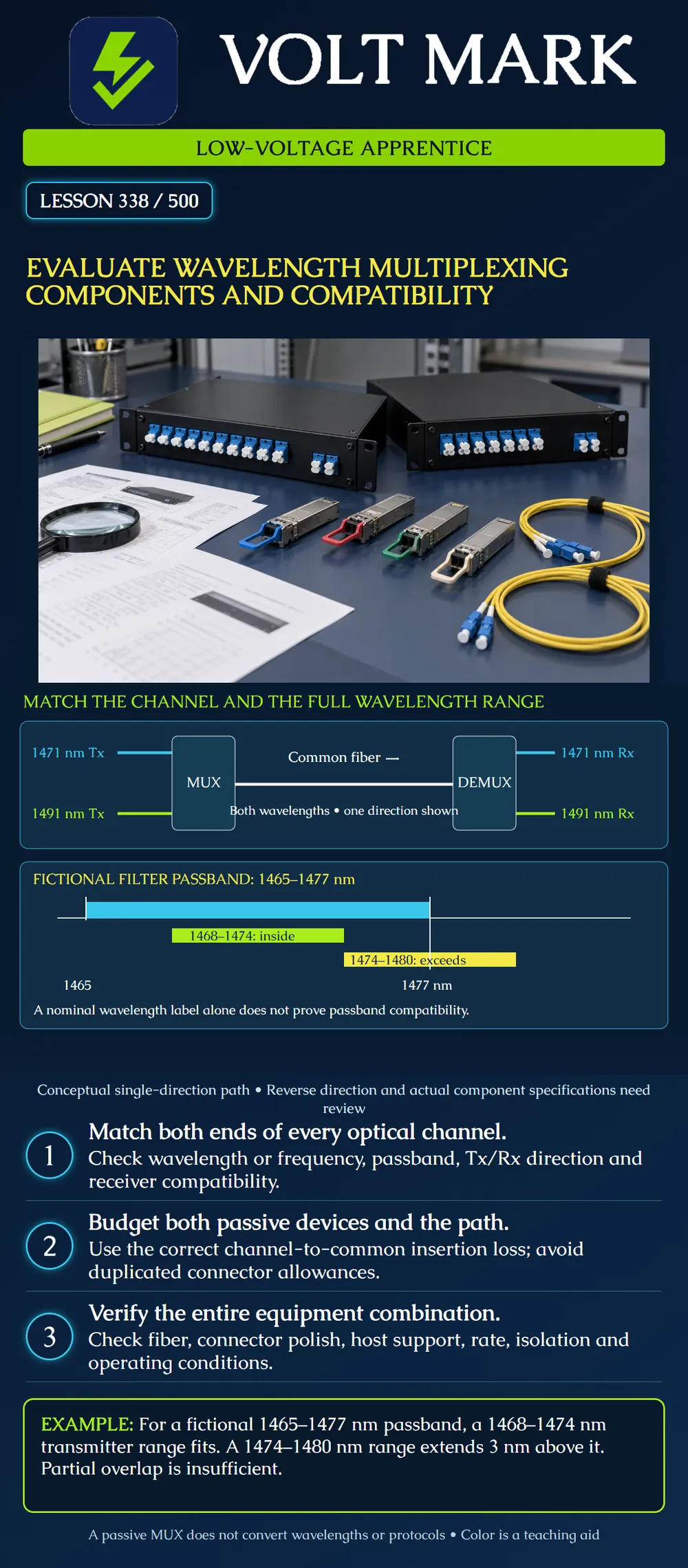
Two illustrative channels, nominally1471 nm and1491 nm, enter the left MUX. Their combined optical path travels along the common fiber to the right DEMUX. The corresponding channel outputs lead to suitable receivers. Cyan and lime distinguish paths; they are not visible laser colors or a universal patch-label scheme.
Only one transmission direction is drawn. A duplex service also needs an explicitly designed reverse path. Do not assume that any common port can be reversed, that all modules use the same fiber count, or that a drawing of one direction establishes a bidirectional system. Consult the actual port diagram.
The nominal wavelengths are teaching labels, not specifications for a selected product. A receiver's acceptable wavelength range, signal format, sensitivity and maximum input all need to match its transmitter and optical path.
Assume a fictional filter guarantees its specified performance from1465 through1477 nm under the stated operating conditions. Candidate A's entire specified transmitter wavelength range is1468–1474 nm. Lower clearance:1468−1465=3 nm. Upper clearance:1477−1474=3 nm. That range is contained within the assumed passband. This resolves only the range-containment check.
Candidate B's specified range is1474–1480 nm. Its upper end exceeds the passband by1480−1477=3 nm. Part of the range overlaps, but full compatibility has not been established. Do not accept the candidate merely because its nominal value sounds close.
The lower diagram uses a common linear wavelength scale. Blue shows the filter interval, lime the contained transmitter interval and yellow the partly out-of-band interval. These are not measured spectra, filter roll-off curves or CWDM standard limits. A real comparison must include the specified temperature and tolerance conditions and any required design margin.
For one fictional channel, assume: MUX channel-to-common insertion loss:1.50 dB. DEMUX common-to-channel insertion loss:1.70 dB. Remaining cable-plant physical loss outside those component boundaries:3.80 dB. Total physical-loss estimate:1.50+1.70+3.80=7.00 dB. Separate future reserve:2.00 dB. Combined allocation:9.00 dB.
Do not count all unused channels' insertion losses in series. Follow the selected input-to-output path. Do not add connector allowances already included in a component's rating. No transceiver limit is supplied here, so9.00 dB is not a pass result.
For each direction and channel, record the transmitter model, nominal wavelength or frequency, full operating range, modulation and data rate, host support, MUX channel port, common port, fiber path, far-end DEMUX port and receiver model. Add component passbands, insertion-loss boundaries, channel isolation, power limits, fiber type, connectors and environmental ratings.
A channel number may depend on a specific wavelength grid. Preserve the manufacturer's frequency or wavelength mapping rather than relying on a bare label such as “channel31.” Similarly, a physical LC or SC fit does not prove that connector polish, fiber or optical function is appropriate. Match the documented interfaces.
Error1: A technician assumes two standard1310 nm transmitters can become separate WDM channels by plugging them into two different colored ports. The passive MUX does not retune either laser; the specified channel plan must already be compatible.
Error2: The correct optical channel reaches a receiver, but the endpoints use incompatible signal rates or protocols. Wavelength routing does not translate that traffic.
Error3: A worksheet treats a monitor or expansion port as an ordinary channel port. The component's actual port function and loss path must be established before using it.
Each case calls for reconciliation of records and specifications, not an unapproved experiment on live equipment.
FOA, DWDM / Wavelength Division Multiplexing: https://www.thefoa.org/tech/dwdm.htm Used for the multiplexing/filter principle from primary indexed text. Cisco, WDM Series Passive Optical System Installation Note: https://www.cisco.com/c/en/us/td/docs/interfaces_modules/transceiver_modules/installation/note/78_16565.html Cisco, Enhanced Wave Division Multiplexing Optical System Installation Note: https://www.cisco.com/c/en/us/td/docs/interfaces_modules/transceiver_modules/installation/note/78_17894.html Primary indexed excerpts support channel matching, passband, isolation and insertion-loss distinctions. Direct Cisco HTML and attempted PDF retrieval redirected to the general support page; full manual inspection is not claimed. Historical products are not recommendations to purchase.
Research checked October1,2026. All numerical examples are original assumptions.
Texas journeyman, 15 questions, scored by topic against the 70% mark. No card, and no account needed to start.
Free study material for low-voltage apprentices. This is a national foundation course: requirements differ by state and by local jurisdiction, and a practice that is common in one place is not a rule everywhere. Nothing here is a licence, a certification, or authority to work unsupervised, and completing it does not count as apprenticeship hours or continuing-education credit. Check the codes adopted where you are working, the licensing authority for that work, and your employer's safety programme. VoltMark is not affiliated with, endorsed by, or sponsored by NFPA, OSHA, NICET, BICSI, FOA, or any state or local licensing authority.

Electrician licensing exam prep: practice questions, timed exam simulations, and step-by-step help finding every answer in the NEC.