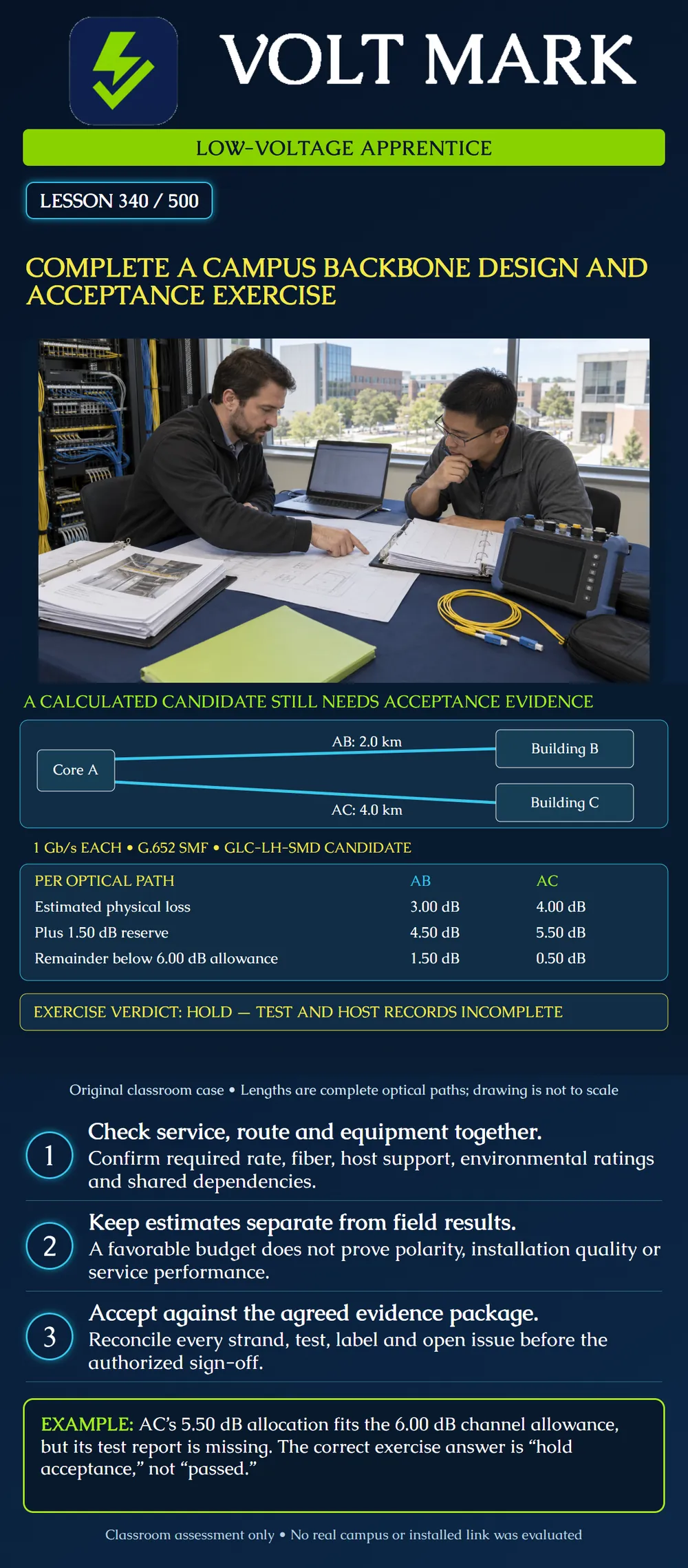
Combine service planning, route review, strand allocation, optical calculations and acceptance evidence into one campus exercise with a worked answer key.
Fictional Building A hosts the campus core. Buildings B and C each need a separate1Gb/s Ethernet uplink. Complete optical-path lengths, including relevant leads and slack, are2.0km for AB and4.0km for AC. Each link uses two G.652 single-mode strands. Candidate optics are Cisco GLC-LH-SMD at both ends.
The drawing is a logical star, not a survey. Each drawn line represents a complete dedicated optical link, not a single strand or a passive split. The exercise route record says both cables use a common entrance enclosure at A. No resilient-path requirement is claimed to be satisfied.
Cisco identifies GLC-LH-SMD as1000BASE-LX/LH. Its table specifies1310nm operation, up to10km over G.652 SMF, a6dB maximum channel insertion-loss allowance, transmit power−9.5 to−3dBm and receive power−20 to−3dBm. The data sheet requires both receiver-power and channel-loss conditions to be met. This exercise retains the published6dB allowance and does not invoke possible shorter-distance exceptions. Actual host and software compatibility remain unverified.
These original teaching assumptions apply separately to each strand and direction: Fiber attenuation allowance at1310nm:0.40dB/km. Four mated connections per path:0.50dB each. AB has two separate splices per path:0.10dB each. AC has four separate splices per path:0.10dB each. Future maintenance reserve:1.50dB for each path. No splitter or WDM component is present. These are fictional component allowances, not Cisco cable ratings or universal installation limits. Calculation and equipment reference boundaries are assumed to match for the exercise.
AB physical estimate: 2.0×0.40 +4×0.50 +2×0.10 =0.80+2.00+0.20=3.00dB. With reserve:3.00+1.50=4.50dB. Unallocated remainder:6.00−4.50=1.50dB.
AC physical estimate: 4.0×0.40 +4×0.50 +4×0.10 =1.60+2.00+0.40=4.00dB. With reserve:4.00+1.50=5.50dB. Unallocated remainder:6.00−5.50=0.50dB.
The length and maximum-loss comparisons are favorable under the assumptions. They do not establish installed performance.
Using minimum transmitter power and the allocations including reserve: AB:−9.5−4.5=−14.0dBm,6dB above the listed−20dBm sensitivity boundary. AC:−9.5−5.5=−15.0dBm,5dB above that boundary.
For a separate high-power illustration, assume independent evidence establishes a1.00dB minimum physical loss for each path under the relevant conditions. Maximum received power is then−3−1=−4dBm,1dB below the−3dBm upper boundary. That minimum is an explicit classroom assumption, not something derived from the maximum-loss inventory or reserve. Actual limits, measurements and operating conditions still require review.
Cable AB strands01–02 serve the B uplink; cable AC strands01–02 serve the C uplink. Each cable has its own unique ID even though strand numbers repeat. The remaining strands require documented allocation and condition records. Map each transmitter to its remote receiver through panel, splice and patch identifiers.
The common A entrance remains a shared failure point. Two uplinks serving two buildings do not form redundant paths for either building. The core equipment and power arrangements also need explicit review.
Record1: AB has a summary stating2.80dB insertion loss, but it does not identify which strand, wavelength, reference method or test direction it covers. Record2: No AC insertion-loss report is supplied. Record3: The host/software compatibility record is missing. Record4: Panel labels and the splice schedule have not been reconciled to an as-built revision. Record5: Required service-functional tests and the cutover/rollback plan have not been signed off by their designated owners.
These are fictional incomplete records. The numerical proximity of2.80dB to AB's3.00dB estimate does not repair its missing identity or test-method information.
The project test plan should specify strands, wavelengths, reference method, test boundaries, applicable limits, uncertainty treatment and required event/reflectance evidence. Link the resulting records to the as-built path IDs. Preserve open items and the party responsible for resolving each one. A link light or an isolated optical power reading is not the whole acceptance package.
Mistake: Accepting both campus links because 4.50 and 5.50 dB fit the ceiling. Correction: Retain that design comparison while separately requiring identified installed tests, compatible hosts and service acceptance records.
Mistake: Assigning the anonymous AB 2.80 dB summary to both strands. Correction: Obtain strand, wavelength, direction and reference-method identity before associating a result with either path.
Mistake: Calling AB and AC redundant links for either building. Correction: Trace the destinations and shared A entrance: each building has only its own illustrated uplink.
Cisco, SFP Modules for Gigabit Ethernet Applications Data Sheet, tables2,3 and product identification: https://www.cisco.com/c/en/us/products/collateral/interfaces-modules/gigabit-ethernet-gbic-sfp-modules/datasheet-c78-366584.html FOA, The Installation Deliverables: https://www.thefoa.org/tech/ref/install/deliverables.html FOA primary indexed text supports the need for documentation and test results as deliverables; no generic test-loss values from that page are adopted.
Sources checked October1,2026. All site descriptions and field records are fictional.
Texas journeyman, 15 questions, scored by topic against the 70% mark. No card, and no account needed to start.
Free study material for low-voltage apprentices. This is a national foundation course: requirements differ by state and by local jurisdiction, and a practice that is common in one place is not a rule everywhere. Nothing here is a licence, a certification, or authority to work unsupervised, and completing it does not count as apprenticeship hours or continuing-education credit. Check the codes adopted where you are working, the licensing authority for that work, and your employer's safety programme. VoltMark is not affiliated with, endorsed by, or sponsored by NFPA, OSHA, NICET, BICSI, FOA, or any state or local licensing authority.

Electrician licensing exam prep: practice questions, timed exam simulations, and step-by-step help finding every answer in the NEC.