Distinguish a suspected interference problem in a data-cable segment from a problem affecting powered endpoints, and explain when an optical link can address the identified path.
Fiber carries the data signal as light through glass. The Cisco/Panduit/Rockwell Automation physical infrastructure guide distinguishes the optical medium’s electrical-noise immunity from the possible susceptibility of optical transceivers [1]. Replacing an identified copper data segment with a properly designed optical link can remove electrical pickup from that glass signal path. It does not make the entire network immune to interference, power disturbances or installation faults.
Cable construction also matters. FOA describes optical cables containing metallic armor or other conductive members and the need to address applicable grounding and bonding [2]. “Fiber” does not necessarily mean an entirely nonconductive cable assembly. Follow the approved design and applicable installation requirements; do not remove protective bonds to investigate an interference theory.
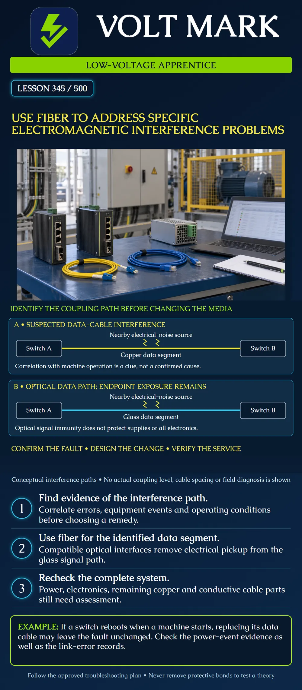
Panel A shows an electrical-noise source near a copper data segment. The wavy symbols represent a suspected interference mechanism, not a measurement or proof of coupling. Panel B replaces the signal segment with glass and compatible optical endpoints. The source remains. Powered switches and optical electronics remain. Their power connections are omitted for clarity, not eliminated. The drawing specifies no spacing, voltage, wavelength, fiber grade or approved routing. It is a diagnostic comparison, not a construction detail.
Record what fails: increasing interface errors, lost sessions, link transitions, device restart, intermittent readings or some other observable event. Identify timestamps and equipment identifiers. Ask which machine modes and environmental conditions coincide with the problem. Correlation helps frame a hypothesis, but it does not establish the cause by itself. A damaged cable, contaminated optical connection, unsupported interface, overload or software event can also affect communications. The review must consider evidence that supports and contradicts the interference hypothesis.
During a fictional review, an interface error counter rises from 18 to 138 over a 20-minute production interval. The increase is 120 errors, or an average of 6 errors per minute during that interval. Another 20-minute interval in a different operating state shows no increase. This difference is a useful observation, not proof that electrical noise caused the errors. Preserve the counter definitions, timestamps and operating conditions. Check whether the counter was reset and whether traffic levels were comparable. Ask the responsible technical lead to evaluate the segment, termination quality, equipment and possible coupling path. The exercise supplies no universal acceptable error threshold.
A switch’s uptime resets at the same time as a machine startup. The team proposes fiber because the route passes near the machine. A reboot is a reason to examine power and device-event evidence as well as the data path. An optical uplink cannot keep the switch operating if its power supply stops supporting it. The apprentice records the events and supplies the evidence to the authorized troubleshooting lead. This case provides no instructions for live power measurements or machine operation.
The reviewer identifies a copper data segment as the relevant path and requests a fiber design. The design packet should specify compatible host interfaces, optical rate and wavelength, fiber type, path length, loss allowance, polarity and environmental suitability. It must also address the endpoint power arrangements and remaining copper connections. Optical connectivity does not automatically satisfy a control system’s timing, availability or recovery requirements. Confirm those requirements separately with the system owner.
The proposed cable has metallic armor. A learner writes “complete electrical isolation” on the drawing because the data travels through glass. That statement exceeds the evidence. Record the cable construction and refer the conductive components and bonding requirements for review. The optical signal path and the cable’s conductive members are different features. Lesson 346 develops that distinction further.
Before a change, record the symptom, baseline counters, traffic conditions, operating state and known competing explanations. For an approved change, record the exact equipment, optical design, implementation plan and rollback provisions. Afterward, verify optical performance and the required service under agreed representative conditions. Compare error increments over clearly identified intervals, device uptime and application behavior. Preserve unresolved findings. A clean short test does not demonstrate immunity under every operating condition. Do not deliberately create faults, disable protections or operate machinery solely for this exercise.
Mistake: Calling the 120-error increase proof that the nearby drive caused interference. Correction: Preserve time, traffic and counter-state evidence and compare competing cable, equipment and power hypotheses.
Mistake: Proposing fiber as the complete cure when the switch uptime resets. Correction: Investigate the power and device-event records through the authorized team as well as the data path.
Mistake: Describing an armored optical cable as total electrical isolation. Correction: Check its construction sheet and other conductive paths; retain the required bonding review for metallic members.
[1] Cisco/Panduit/Rockwell Automation, Physical Infrastructure for the Converged Plantwide Ethernet Architecture, February 2023, fiber/copper considerations and optical-transceiver susceptibility note: https://www.cisco.com/c/en/us/td/docs/sanity/suman/CPwE-Physical-Infrastructure_Feb2023.html [2] Fiber Optic Association, Outside Plant Fiber Optic Cables, metallic armor and grounding/bonding discussion: https://www.thefoa.org/tech/ref/OSP/cable.html Accessed 2026-10-01. Cisco primary HTML was inspected; FOA primary indexed excerpts support the cable-construction distinction. No universal separation distance or site-specific bonding arrangement is derived here. Cases, numbers, worksheet and questions are original.
Texas journeyman, 15 questions, scored by topic against the 70% mark. No card, and no account needed to start.
Free study material for low-voltage apprentices. This is a national foundation course: requirements differ by state and by local jurisdiction, and a practice that is common in one place is not a rule everywhere. Nothing here is a licence, a certification, or authority to work unsupervised, and completing it does not count as apprenticeship hours or continuing-education credit. Check the codes adopted where you are working, the licensing authority for that work, and your employer's safety programme. VoltMark is not affiliated with, endorsed by, or sponsored by NFPA, OSHA, NICET, BICSI, FOA, or any state or local licensing authority.

Electrician licensing exam prep: practice questions, timed exam simulations, and step-by-step help finding every answer in the NEC.