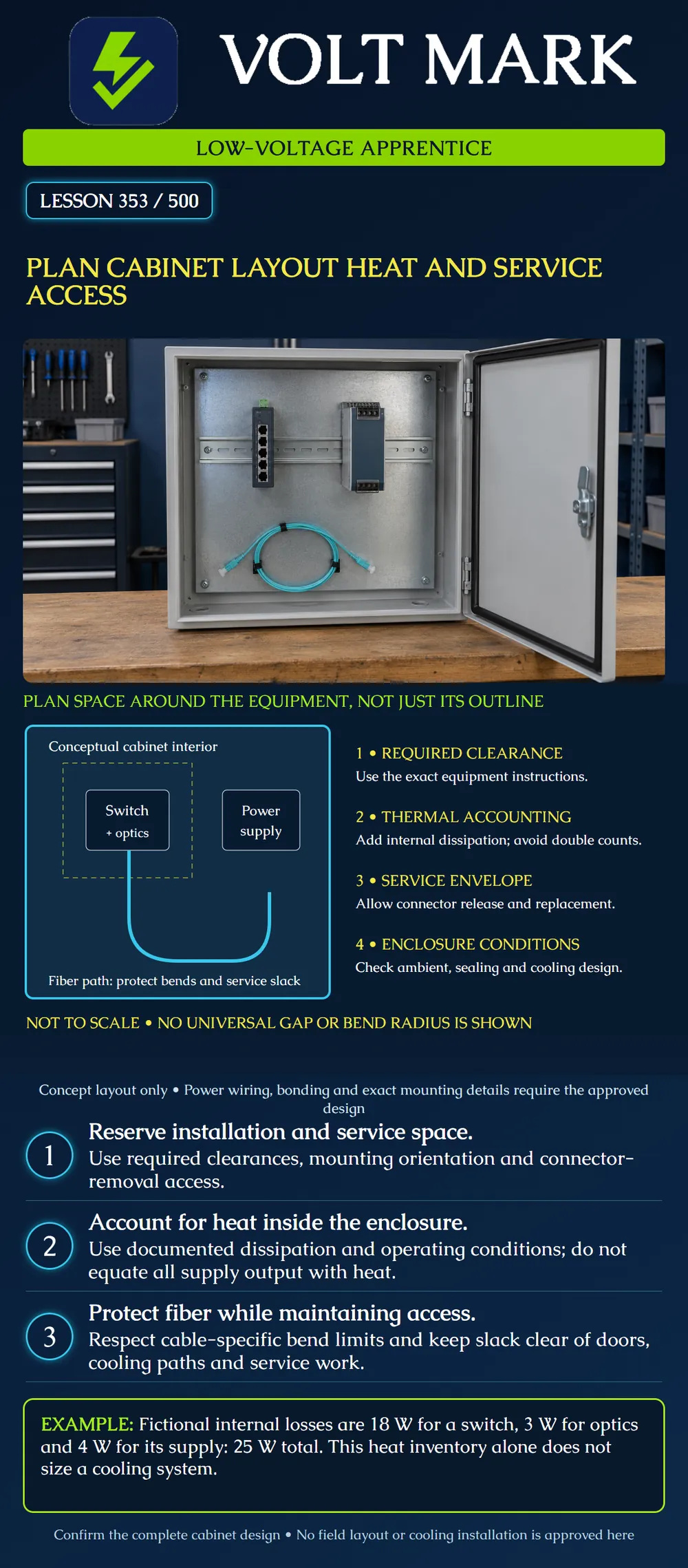
Review an industrial low-voltage cabinet concept for equipment clearance, heat accounting, fiber handling and maintainable access.
The left panel is a conceptual cabinet interior. The dashed yellow boundary around the switch represents space that must be established from its installation instructions; it is not a dimensioned clearance. The cyan curve is a fiber-routing concept, not a specified bend radius. The power-supply block reminds the learner that supporting equipment occupies space and produces heat. Its placement is not a recommendation for a particular model or mounting orientation. Power wiring, protective bonding and construction details are omitted.
Cisco’s IE3100 installation guide calls for access that allows indicators to be read and ports/cabling to remain accessible, and it addresses the equipment’s surrounding operating environment [1]. These instructions illustrate why the installed equipment outline is smaller than its practical installation and service envelope. Rittal’s thermal-planning material identifies internal heat losses, enclosure characteristics and environmental conditions as inputs to climate-control planning [2]. A simple sum of watts is an input, not a complete cooling design.
Start with the enclosure and exact equipment dimensions. Add manufacturer-required clearances and the approved mounting orientation. Account for terminals, cable entries, connector bodies, release latches, optical-module extraction and the tools needed for authorized service. A connector may fit with the door open but be pressed against the door when it closes. A switch may fit between adjacent devices but be impossible to remove without disturbing unrelated connections. Review these conditions before the layout is released.
A fictional switch body is 60 mm wide. Its supplied installation instructions require 25 mm clearance on each side for this example. The reserved width is 60 + 25 + 25 = 110 mm. This calculation does not establish vertical or front clearance. Nor does it prove that an adjacent device may occupy a neighboring thermal or service envelope. All these example dimensions are invented teaching inputs, not requirements for the illustrated Cisco product or any real switch.
List documented heat dissipated inside the cabinet under the intended operating conditions. Avoid counting the same loss twice. Original example: the fictional switch’s stated 18 W excludes optics. Two installed optics add 3 W total. The supply contributes 4 W of conversion loss. These three internal heat contributions total 18 + 3 + 4 = 25 W. If the switch’s 18 W had already included the optics, adding 3 W again would be a double count. The resulting inventory would instead be 18 + 4 = 22 W. Preserve the scope of each source value.
A supply’s electrical output is not automatically all heat in the cabinet. Some output may feed loads elsewhere; some powers local equipment whose heat is already listed. Identify where energy is dissipated and what each manufacturer figure includes. Likewise, a PoE switch’s total input may include power delivered to remote devices. Do not count that exported load entirely as local cabinet heat while also counting the switch’s separately specified dissipation. This lesson does not determine a real thermal balance or prescribe a cooling capacity.
The packet includes the 25 W internal inventory but omits outside ambient range, enclosure dimensions and material, installation surroundings, solar exposure and allowable internal temperature. Mark the thermal review incomplete. A larger wattage-rated fan or cooling unit chosen by guesswork does not resolve those missing inputs. The responsible designer must evaluate the enclosure, environmental protection and cooling method together.
Use the cable and connector manufacturers’ applicable bend and handling limits. Distinguish installation/loading conditions from final service conditions where the instructions do so. Plan supported slack that can be accessed without pulling on connectors. Keep it away from door hinges, sharp edges and locations where maintenance can crush it. Allow access to labels, adapters and optical inspection/cleaning work under the site procedure. A neatly drawn loop is not evidence that its radius is acceptable. Record the actual cable type and the dimensioned routing detail in the approved design.
Do not assume that adding openings or a fan preserves the enclosure’s required protection. The cabinet may need to control moisture, dust or contaminants as well as temperature. Any proposed thermal change must be evaluated with those requirements and the equipment installation instructions. Do not use a closed-door temperature observation from one operating state as proof of all seasonal or load conditions.
Record enclosure identity, internal dimensions, mounting layout, required clearances, equipment orientation, service-access envelope, fiber routing and bend references, cable entries, internal heat inventory, operating environment, cooling design reference and unresolved items. Link the drawing revision to the equipment list. A replacement power supply or optical module can alter the space and thermal review even if the network function remains similar.
Mistake: Reserving only the switch's 60 mm body width. Correction: Include the fictional 25 mm side clearances: reserve 110 mm, then separately check front, vertical and service access.
Mistake: Adding optic power twice or treating exported PoE power as cabinet heat. Correction: Record what each dissipation figure includes and where power is used before totaling internal heat.
Mistake: Selecting a fan from the 25 W heat inventory alone. Correction: Obtain ambient, enclosure and allowed internal-temperature evidence, and review cooling together with ingress protection.
[1] Cisco Catalyst IE3100 Rugged Series Switches Hardware Installation Guide, Switch Installation: https://www.cisco.com/c/en/us/td/docs/switches/lan/cisco_ie3100/installation/ie3100-hw-install-guide/m-ie3100-switch-installation.html Primary HTML access/clearance guidance inspected. [2] Rittal, Free Calculation Program for the Climate Control of Enclosures: https://blog.rittal.com.au/blog/free-calculation-program-for-the-climatecontrol-of-enclosures Primary indexed text inspected for enclosure surface/heat-loss planning concepts only; no software was run or thermal certificate produced. Accessed 2026-10-01. Dimensions, losses, cases and worksheet are original fictional examples.
Texas journeyman, 15 questions, scored by topic against the 70% mark. No card, and no account needed to start.
Free study material for low-voltage apprentices. This is a national foundation course: requirements differ by state and by local jurisdiction, and a practice that is common in one place is not a rule everywhere. Nothing here is a licence, a certification, or authority to work unsupervised, and completing it does not count as apprenticeship hours or continuing-education credit. Check the codes adopted where you are working, the licensing authority for that work, and your employer's safety programme. VoltMark is not affiliated with, endorsed by, or sponsored by NFPA, OSHA, NICET, BICSI, FOA, or any state or local licensing authority.

Electrician licensing exam prep: practice questions, timed exam simulations, and step-by-step help finding every answer in the NEC.