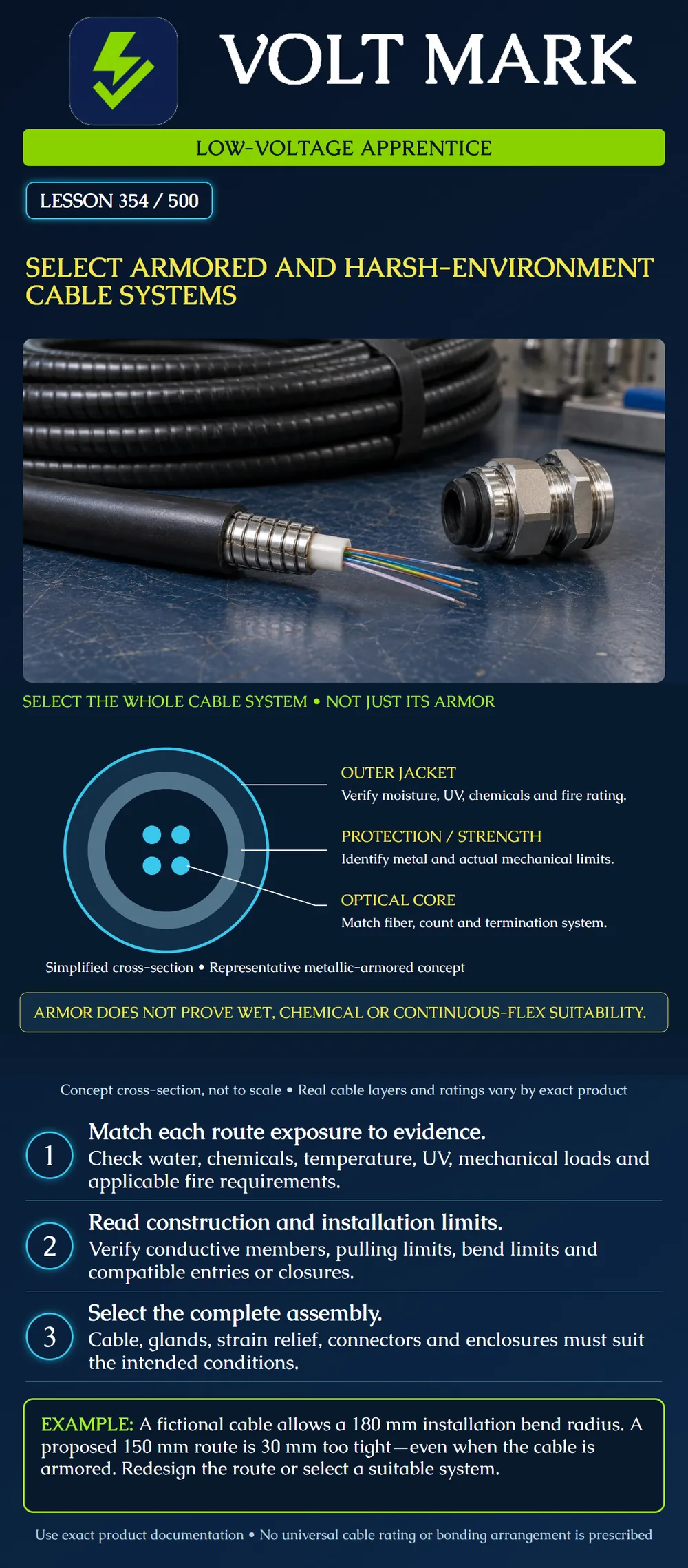
Compare cable construction and documented ratings against a route’s specific exposures, then identify the compatible termination and installation system.
The illustration separates an outer jacket, a representative metallic protective layer and an optical core. It is deliberately simplified: real cables may contain buffers, tubes, water-blocking materials, strength members and additional jackets. The leader lines connect each part to a different selection question. No layer alone establishes suitability for every industrial exposure. The sketch does not specify a real cable’s dimensions or material properties.
FOA’s outside-plant cable reference discusses different cable constructions, environmental protection and conductive armor considerations [1]. Corning’s steel-armored cable installation guidance directs the installer to the cable specification for mechanical limits, including bend radius and tensile strength [2]. Corning product-family documentation also separates storage, installation and operating temperature ranges [3]. These examples support product-specific selection. They are not blanket approval for an armored cable in any route.
Identify indoor and outdoor sections, wet locations, sunlight, chemical contact, temperature conditions, impact/crush exposure, movement and installation method. Record applicable building/fire requirements separately from environmental suitability. A product described as outdoor does not by that word alone establish suitability for every indoor space. Likewise, a jacket description such as low-smoke zero-halogen does not by itself prove every required U.S. fire classification. Use the exact markings and applicable project requirements.
Armor can contribute protection against particular mechanical exposures, but the documented test conditions and limits matter. Identify whether protection is metallic or nonmetallic and whether other conductive members exist. Review pulling tension, bending, crushing and support requirements using the manufacturer’s information. Do not treat armor as permission to exceed a bend limit or pull on an unsuitable component. Any conductive construction must be handled under the approved applicable bonding/grounding design. This lesson supplies no universal bonding location or conductor size.
A fictional cable’s installation instructions specify a minimum installation bend radius of 180 mm. The proposed route has a 150 mm radius. The route is 30 mm below the required minimum: 180 − 150 = 30 mm. It does not pass this screen. The corresponding diameters are 360 mm and 300 mm respectively; do not confuse radius with diameter when comparing a drawing or guide. The supplied fictional final-service radius is 120 mm. That smaller figure does not authorize the 150 mm bend during installation. Apply the limit for the actual condition. These numbers are not specifications of the Corning sources.
A cable is documented for the intended temperature and mechanical loads. The cleaning product at the site has not been included in the compatibility evidence. Record the product, concentration, temperature, contact duration and frequency, then obtain the appropriate manufacturer assessment. Mark chemical suitability unresolved. Do not infer it from an armored construction or from the jacket looking intact during a short visit.
The selected fictional cable has an outside diameter of 12 mm. A proposed gland’s documented clamping range is 6 through 10 mm. Twelve millimeters is outside that range. Do not force the cable into the gland or remove its jacket to make it fit. Select a compatible entry arrangement through the design process, considering sealing, retention, construction and required ratings. A suitable cable cannot compensate for an unsuitable entry.
A catalog says “armored industrial cable,” but gives no continuous-flex or torsion rating for the proposed moving machine section. Record the motion requirement and the missing evidence. The cable’s static installation suitability does not establish machine-motion life. Rated moving assemblies are addressed in lesson 355.
Match fiber type and strand count to the optical design. Then reconcile cable diameter, termination method, closures, glands, strain relief, mounting and maintenance access. Check compatibility at transitions between differently protected sections. Keep the cable construction sheet and installation procedure with the project records. Record the exact part number and revision; a family description may include several constructions with different limits.
For each route segment, enter exposure, required rating or limit, candidate evidence, installation condition, termination components and unresolved questions. Use separate rows for temperature, moisture, UV, chemicals, fire requirements, mechanical loads, bend radius, movement, conductive components and optical compatibility. A favorable row does not cancel an unfavorable one. “Not documented” is an evidence gap, not an invented pass.
Mistake: Using the 120 mm service bend limit during a 150 mm installation bend. Correction: Apply the stated 180 mm installation radius for that condition; the proposed bend is 30 mm too tight.
Mistake: Assuming armor establishes resistance to the site's cleaner or repeated motion. Correction: Obtain separate chemical and motion suitability evidence for the actual route exposures.
Mistake: Forcing a 12 mm cable into a gland rated for 6–10 mm. Correction: Request a compatible entry system with documented sealing and retention; do not strip the jacket to make it fit.
[1] Fiber Optic Association, Outside Plant Fiber Optic Cables: https://www.thefoa.org/tech/ref/OSP/cable.html Primary page inspected for construction distinctions. [2] Corning, Duct Installation of Fiber Optic LSZH Steel Armor Cable: https://www.corning.com/catalog/coc/documents/standard-recommended-procedures/S46998-A0007-P158.pdf Primary indexed text inspected for the direction to use cable-specific mechanical limits. [3] Corning, Industrial LSZH Indoor/Outdoor, Tray-Rated, Gel-Free, Interlocking Armored Cables: https://www.corning.com/catalog/coc/documents/product-family-specifications/0045_NAFTA_AEN.pdf Primary indexed specifications inspected for separate temperature categories. No numerical product limit is generalized here. Accessed 2026-10-01. All worked values, cases and worksheet are original fictional teaching inputs.
Texas journeyman, 15 questions, scored by topic against the 70% mark. No card, and no account needed to start.
Free study material for low-voltage apprentices. This is a national foundation course: requirements differ by state and by local jurisdiction, and a practice that is common in one place is not a rule everywhere. Nothing here is a licence, a certification, or authority to work unsupervised, and completing it does not count as apprenticeship hours or continuing-education credit. Check the codes adopted where you are working, the licensing authority for that work, and your employer's safety programme. VoltMark is not affiliated with, endorsed by, or sponsored by NFPA, OSHA, NICET, BICSI, FOA, or any state or local licensing authority.

Electrician licensing exam prep: practice questions, timed exam simulations, and step-by-step help finding every answer in the NEC.