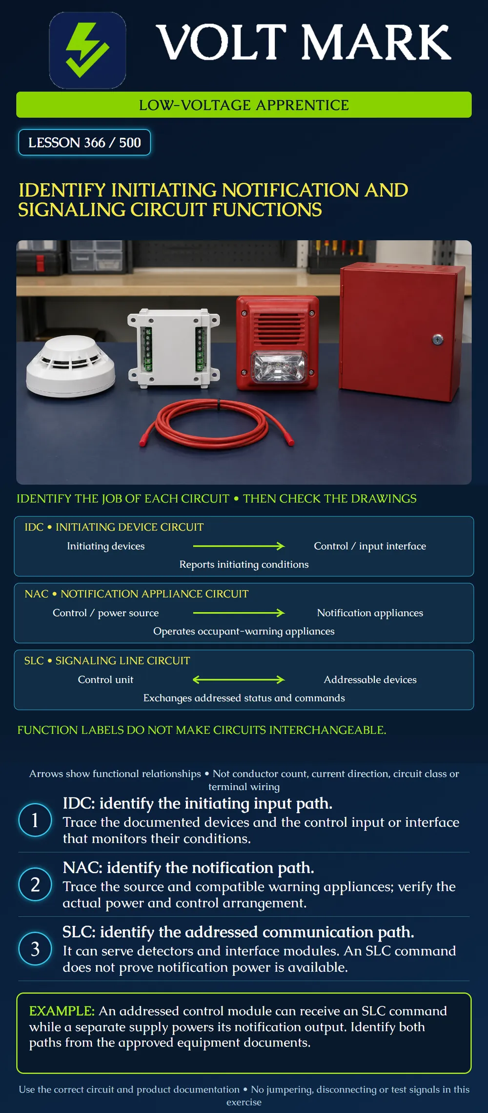
Recognize the functions of an initiating device circuit (IDC), notification appliance circuit (NAC) and signaling line circuit (SLC). Trace a functional path on approved documents without confusing its name with a complete wiring specification.
An IDC conveys initiating-device conditions to a control input or interface. A NAC serves notification appliances that warn occupants. An SLC provides signaling between a control unit and addressable devices, including detectors and interface modules. NFPA's public Fire Alarm Basics illustrates these roles. These labels identify functions; they do not, by themselves, specify circuit class, conductor count, power limitation, cable type or permitted topology.
The IDC arrow shows information reaching the input side. The NAC arrow shows the relationship between its source and warning appliances. The SLC's two-way arrow represents addressed communication. None of the arrows denotes current direction or a complete physical circuit. Actual systems may have additional supplies, modules and other connections omitted here.
An initiating device need not connect directly to a panel-mounted IDC. An approved interface can connect an initiating group to an addressable system. Likewise, a notification circuit can be associated with supported remote equipment. Identify the actual source and interface instead of assuming every line ends directly at the same enclosure.
The fictional training drawing contains these records:
S-01: communication between the control unit and addressed devices, including M-01 and output module M-02. N-01: notification appliances operated through M-02 using the documented external supply P-01.
Label the initiating group path IDC, the addressed communication path SLC and the shown appliance path NAC. This is a functional classification exercise. It does not assign a real model, conductor count, output rating or approved wiring configuration.
Honeywell's FCM-1 descriptions give a real product example of an addressed control module serving externally powered notification loads. The lesson's fictional arrangement uses that distinction conceptually, not as a copied installation design. An available communication command and available load power are separate facts. A learner must locate both in the applicable documentation.
Suppose a training log reports that M-02 received a command, while the appliance-operation record is missing. You can record the command evidence, but cannot conclude N-01 operated correctly. The source, module, appliance circuit and appliances still require their applicable verification. No live test is authorized by this paper exercise.
Two red cable jackets do not prove two circuits perform the same job. Two conductors do not prove a circuit is an IDC, NAC or SLC. Use approved drawings, equipment terminal designations and manufacturer instructions. If records conflict with a label, document the discrepancy and refer it for resolution; do not try unknown terminals to discover what happens.
A learner says, “It has a detector, so it must be an IDC.” The drawing actually shows an addressed detector on S-01. Device purpose and circuit function are related, but the word detector alone does not establish the pathway classification. Identify the actual interface and documented signaling arrangement.
M-01 is addressed on S-01 and monitors the conventional initiating group I-01. The two sides have different functions. Do not rename I-01 an SLC simply because its information eventually reaches the control unit through S-01. The module connects functional domains; it does not make every connected circuit interchangeable.
A training enclosure drawing includes SLC terminals, an output connection and a separate supply connection. A learner assumes adjacent terminals carry the same voltage or may be jumpered. There is no basis for that assumption. The proper next action is to use the exact model's approved connection information and authorized work procedure. This lesson intentionally supplies no terminal numbers or jumpers.
For each path, the project reviewer still needs:
Record unknown fields honestly. Do not assign a fault classification from the fact that a drawing happens to show a loop. Do not assign power-limited status simply because the system is called low voltage. The next lesson addresses that distinction.
The fictional drawing has two initiating groups, one SLC and three notification circuits. The worksheet therefore has six functional circuit entries: 2 + 1 + 3 = 6. That count is not a conductor count, a cable quantity or a load calculation. It excludes any separate supply feeds unless the actual inventory explicitly includes them. Define what you are counting before calculating materials.
Provide the drawing reference, circuit label, connected point/group, source/interface and unresolved question. For example: “Drawing FA-2 rev C identifies N-01 at M-02. The copy supplied does not identify the external supply record. Please provide the approved supply reference.” That is a reviewable request. “NAC is broken” is an unsupported diagnosis when no test evidence has been supplied.
These circuit terms support nationwide learning. Actual installation and inspection must use the adopted requirements, approved design and the manufacturer's documents for the installed system. Modern products can combine capabilities in ways a simplified teaching diagram does not show. Do not assume every speaker, strobe or addressed appliance uses the same circuit arrangement.
Mistake: Calling every detector connection an IDC. Correction: Trace the actual interface: an addressed detector can communicate on an SLC, while a module can monitor a separate IDC.
Mistake: Treating M-02's received command as proof that its externally powered appliances operated. Correction: Identify the supply and retain the required NAC and appliance-operation evidence as separate checks.
Mistake: Using the six functional entries to order six identical cables. Correction: Obtain the approved circuit details and route inventory; functional counts do not specify conductors or cable quantities.
NFPA, A Guide to Fire Alarm Basics: https://www.nfpa.org/-/media/project/storefront/catalog/files/code-or-topic-fact-sheets/FireAlarmBasicsFactSheet.pdf Scope: primary indexed circuit-function overview; no universal wiring configuration inferred. Honeywell NOTIFIER, Fire Alarm Modules: https://www.honeywellbuildings.com/fire/fire-detection-and-alarm-system/notifier/modules Honeywell, Flashscan Intelligent Addressable Control Module: https://buildings.honeywell.com/gb/en/products/by-category/fire-life-safety/i-o-modules/control-modules/flashscan-intelligent-addressable-control-module Scope: primary manufacturer description of addressed control and external load power. Regional product descriptions are used only to illustrate the functional distinction, not U.S. installation approval or product selection. All project labels, scenarios, counting examples and artwork are original educational material.
Texas journeyman, 15 questions, scored by topic against the 70% mark. No card, and no account needed to start.
Free study material for low-voltage apprentices. This is a national foundation course: requirements differ by state and by local jurisdiction, and a practice that is common in one place is not a rule everywhere. Nothing here is a licence, a certification, or authority to work unsupervised, and completing it does not count as apprenticeship hours or continuing-education credit. Check the codes adopted where you are working, the licensing authority for that work, and your employer's safety programme. VoltMark is not affiliated with, endorsed by, or sponsored by NFPA, OSHA, NICET, BICSI, FOA, or any state or local licensing authority.

Electrician licensing exam prep: practice questions, timed exam simulations, and step-by-step help finding every answer in the NEC.