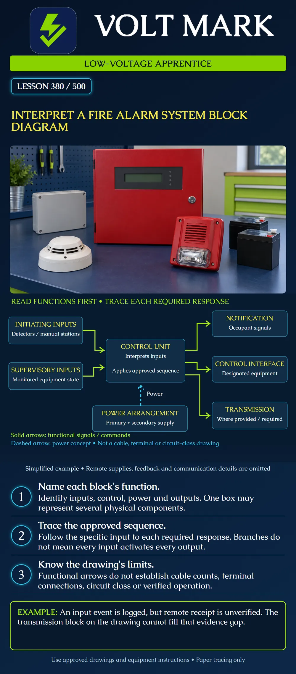
Read a functional fire alarm diagram without confusing it with a wiring drawing, equipment schedule or acceptance record. Trace a specified input through the approved sequence and identify the separate evidence needed for its required responses.
A block diagram groups functions. A box can represent one component, multiple components or a subsystem. Lines show relationships according to the legend. Their meaning must be established before they are used to make decisions.
On this poster, solid lime arrows represent functional signals or commands. The dashed cyan arrow represents a power concept. Neither type represents a conductor count, cable route, polarity or circuit classification. The diagram is an original teaching example, not a construction document.
NFPA's Fire Alarm Basics overview distinguishes initiation, supervision, power, notification, emergency control functions and off-premises signaling. The control unit receives information and applies its configured logic. Initiating examples include detectors and manual stations; supervisory examples include monitored equipment conditions.
The poster places notification, control interfaces and transmission on separate branches. These functions have different purposes and need distinct evidence. Transmission is shown where provided or required; the drawing does not assert that every system has the same remote service.
The power box identifies primary and secondary supply concepts without specifying a particular source design. Actual systems may have separate power supplies and other arrangements. A single arrow into the control unit is not a claim that the control unit directly supplies every component.
Begin with a named input and the approved sequence, not with the assumption that all arrows activate together. Establish the intended event class, notification area, control action and transmission behavior. Then identify the documents that define each part.
For a fictional training case, input M-01 is assigned three required results in a provided classroom sequence: notification zone N-01, a specified control interface EC-01 and transmission to the assigned receiving service. This invented sequence is not a universal rule for manual stations. A real project requires its actual approved matrix.
Trace M-01 to the control unit, then trace each assigned branch separately. Ask what equipment and evidence sit behind each block. Do not infer that a line ending at "transmission" proves the message reached a recipient.
The block diagram explains overall relationships. A riser or pathway drawing may show floor-to-floor arrangement. A wiring detail identifies connections for particular equipment. A device schedule identifies components. Calculations address matters such as loading and capacity. The approved sequence describes required behavior.
No one of these automatically substitutes for the others. If a functional line reaches a remote supply or interface, find the corresponding detail and schedule. Do not invent a connection based on proximity in the picture.
Case A — Counting wires from arrows: A learner sees three outgoing branches and orders three identical cables. The diagram does not support that material count. Find the approved circuit details, routes and specifications.
Case B — Every input, every output: A reviewer assumes each supervisory input operates all occupant notification. The branches do not establish this. Read the approved event/response matrix for the specific input.
Case C — Input proven, output missing: An archived report logs M-01 but contains no N-01 result. The input record cannot prove notification. Request the missing verification evidence through the responsible process.
Case D — Interface command only: A record shows EC-01 commanded. Its designated equipment's physical response is not documented. Keep the interface command and the receiving equipment result separate.
Case E — Transmission icon mistaken for dispatch: The diagram contains a remote-transmission block. That neither proves receipt nor establishes that emergency responders were dispatched. The service arrangement and actual records determine what happened.
Case F — Power box oversimplified: A separate field power supply appears in the equipment schedule but not in the classroom sketch. The approved project documents govern. Do not remove the supply or assume the sketch establishes capacity.
Case G — Diagram revisions disagree: The system block diagram references one interface identifier while the current schedule uses another. Record both revisions and request reconciliation. Do not silently choose the more convenient version.
For each branch, record the input identifier, event class, sequence reference, destination function, equipment reference, required result, evidence source and unresolved question.
Paper exercise: two fictional initiating events each require three separately documented responses. Six response records are expected. Five are present, leaving one missing. That is one unresolved evidence item, not automatically one failed appliance. The exercise's scope is invented and must not be used as a real test requirement.
Add a separate list of documents needed before installation: applicable approved drawings, current equipment instructions, compatibility documentation, schedules, calculations and sequence. Identify a reviewer for discrepancies. Do not write terminal numbers onto the learning diagram from memory.
Mistake: Ordering one identical cable for each functional arrow. Correction: Use the legend and then locate the approved wiring, pathway and circuit specifications for material quantities.
Mistake: Assuming every initiating or supervisory event activates every output branch. Correction: Trace the named input through its actual approved sequence and identify each required response.
Mistake: Closing the whole event row from its input log or interface command. Correction: Retain separate evidence for notification, the required equipment result and transmission receipt within their respective scopes.
NFPA, A Guide to Fire Alarm Basics, opened official primary PDF. Used for the system-function overview. The poster and teaching cases are original; no wiring design, adopted-code determination or universal event sequence is taken from the overview. https://www.nfpa.org/-/media/project/storefront/catalog/files/code-or-topic-fact-sheets/FireAlarmBasicsFactSheet.pdf
National fundamentals; actual system design follows applicable requirements and approved project documents.
Texas journeyman, 15 questions, scored by topic against the 70% mark. No card, and no account needed to start.
Free study material for low-voltage apprentices. This is a national foundation course: requirements differ by state and by local jurisdiction, and a practice that is common in one place is not a rule everywhere. Nothing here is a licence, a certification, or authority to work unsupervised, and completing it does not count as apprenticeship hours or continuing-education credit. Check the codes adopted where you are working, the licensing authority for that work, and your employer's safety programme. VoltMark is not affiliated with, endorsed by, or sponsored by NFPA, OSHA, NICET, BICSI, FOA, or any state or local licensing authority.

Electrician licensing exam prep: practice questions, timed exam simulations, and step-by-step help finding every answer in the NEC.