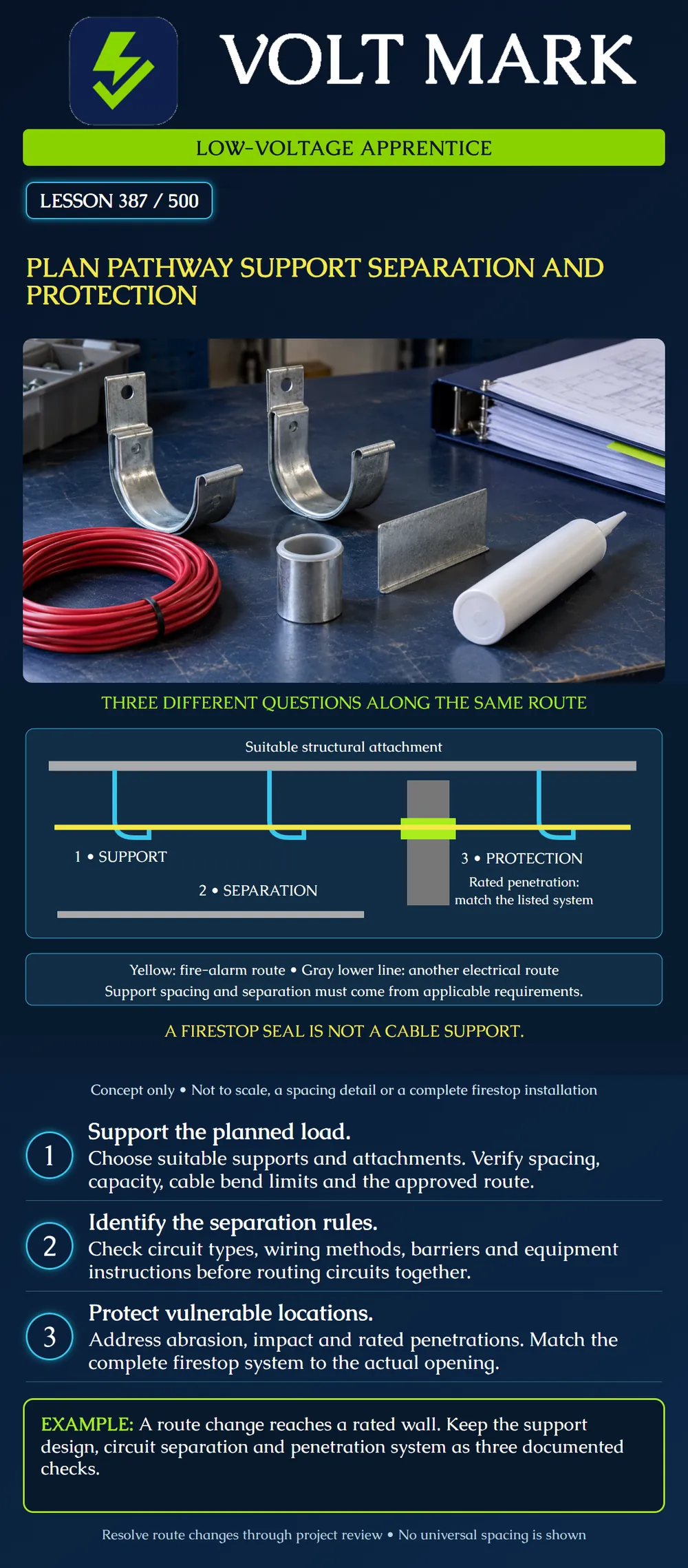
Explain three independent questions when planning a fire-alarm pathway: what carries its load, what other circuits it may approach or share space with, and how the cable and building barriers are protected. Use the approved design and the requirements applicable to the actual installation.
Begin with the actual cable schedule, route and installation conditions. Identify the support product, attachment, supporting structure and required spacing. Check cable weight and permitted capacity without assuming that a tray, hook or fastening point has unlimited reserve.
nVent's Cat HP support information lists product-dependent capacity and load information. It is useful as an example of the fields a support selection needs, not proof that a particular hook is acceptable for every fire-alarm circuit. Cable count ratings based on one cable size do not automatically describe a different bundle.
Plan changes in direction, entries and transitions. Obtain cable bending and pulling limits from the exact cable documentation. Supports should not create a damaging pinch or sharp turn. A bundle that fits physically may still exceed the selected support's permitted load or cable capacity.
Do not assume an existing ceiling grid, another trade's pipe, duct or cable is an approved attachment point. Identify the attachment method in the applicable design and installation requirements. Where a route cannot follow the documented arrangement, record the conflict for resolution rather than borrowing a nearby object as a support.
“Low voltage” is not enough information to decide whether two circuits can occupy a raceway, tray, box or cabinet. Identify each circuit's classification and the applicable separation provisions. Note the wiring method, enclosure arrangement and any required barrier.
For a concrete manufacturer example, the Gamewell-FCI E3 Series UL listing document, revision J dated September 3, 2021, section 4, describes a minimum quarter-inch separation between its Class 2 power-limited and non-power-limited field wiring, with specific cabinet routing diagrams. That is an equipment-document example. It is not a general spacing rule for every open cable run in a building.
Read the diagram notes as well as the numeric clearance. A manufacturer's identified wiring zones, exceptions or circuit markings matter. Never transfer the cabinet example to a different product without checking that product's instructions. Never translate an example into permission to open or rewire energized equipment.
For each shared-pathway proposal, record both circuit types and the basis that permits the arrangement. When required evidence is missing, mark the proposed sharing unresolved. A convenient route is not a documented exception.
Identify places where cable could encounter impact, sharp edges, crushing, movement, moisture or other environmental conditions. Select the required protection through the approved design and product instructions. Physical protection, cable environmental suitability and electrical separation are separate checks.
At a rated wall or floor, identify the actual assembly and penetrants before selecting a firestop detail. UL's application guide explains that the rating belongs to the complete system, including its specified construction and materials. Components are not freely interchangeable. A sleeve by itself does not establish a completed firestop.
The same guide explains that where a system calls for rigidly supported penetrating items, the design must treat the firestop as providing no support. Do not count the seal as a hanger. Verify the support and penetration requirements together without substituting one for the other.
For an original classroom case, a planned corridor route shifts around a new duct and reaches a different wall opening. The apprentice's comparison record should identify:
Do not label the route accepted while those questions remain unanswered. A photograph can help locate a conflict, but it cannot alone establish concealed construction, structural capacity or the listed firestop design.
For an imaginary drawing, the original path has straight segments of 18 ft, 12 ft and 9 ft. Its geometric length is 18 + 12 + 9 = 39 ft. A documented sketch adds a 3 ft approach and a 3 ft return around an obstruction: 39 + 3 + 3 = 45 ft, an increase of 6 ft.
This arithmetic is route measurement only. It does not calculate an installed cable order, allowance, voltage drop, support count or permissible bend. Those need their own inputs. Do not estimate support count from these numbers without a verified spacing requirement and transition details.
Primary sources consulted October 1, 2026: nVent CADDY Cat HP J-Hook product page; opened. Product fields illustrate support-selection evidence, not blanket fire-alarm approval: https://www.nvent.com/en-ca/caddy/products/efscat21hpwh nVent Cable Support Systems catalog; indexed excerpts only, direct PDF open failed: https://www.nvent.com/sites/default/files/dam/f1185b-wwen.pdf Gamewell-FCI E3 Series Fire System UL Listing Document, LS10080-051GF-E:J, September 3, 2021, section 4, printed page 51; opened: https://prod-edam.honeywell.com/content/dam/honeywell-edam/hbt/en-us/documents/manuals-and-guides/ul-listed-documents/gamewell/hon-ba-fire-ls10080-051gf-e-j-e3-ulld.pdf UL Solutions Firestop and Joint Application Guide, 2024, pages 3, 5 and 6; opened: https://www.ul.com/sites/default/files/2024-10/Firestop-and-Joint-application-guide-final-draft-4-29-24pm-1.pdf Hilti USA Firestop Resource Center; opened as a system-documentation resource: https://www.hilti.com/content/landing-page/local/firestop-resource-center
The diagram and scenarios are original learning aids. No universal NEC separation distance or support interval is asserted. Verify adopted requirements, project specifications and current instructions for the installation.
Mistake: Estimating support capacity from whether the bundle fits inside a hook. Correction: Check the selected support, attachment and structure against documented load and cable-capacity limits.
Mistake: Applying a cabinet separation dimension to every building pathway. Correction: Identify both circuit classifications, wiring methods and the applicable separation requirement for that location.
Mistake: Using the firestop material to carry the penetrating cable. Correction: Provide the support required by the applicable system and keep the penetration assembly's function separate.
Texas journeyman, 15 questions, scored by topic against the 70% mark. No card, and no account needed to start.
Free study material for low-voltage apprentices. This is a national foundation course: requirements differ by state and by local jurisdiction, and a practice that is common in one place is not a rule everywhere. Nothing here is a licence, a certification, or authority to work unsupervised, and completing it does not count as apprenticeship hours or continuing-education credit. Check the codes adopted where you are working, the licensing authority for that work, and your employer's safety programme. VoltMark is not affiliated with, endorsed by, or sponsored by NFPA, OSHA, NICET, BICSI, FOA, or any state or local licensing authority.

Electrician licensing exam prep: practice questions, timed exam simulations, and step-by-step help finding every answer in the NEC.