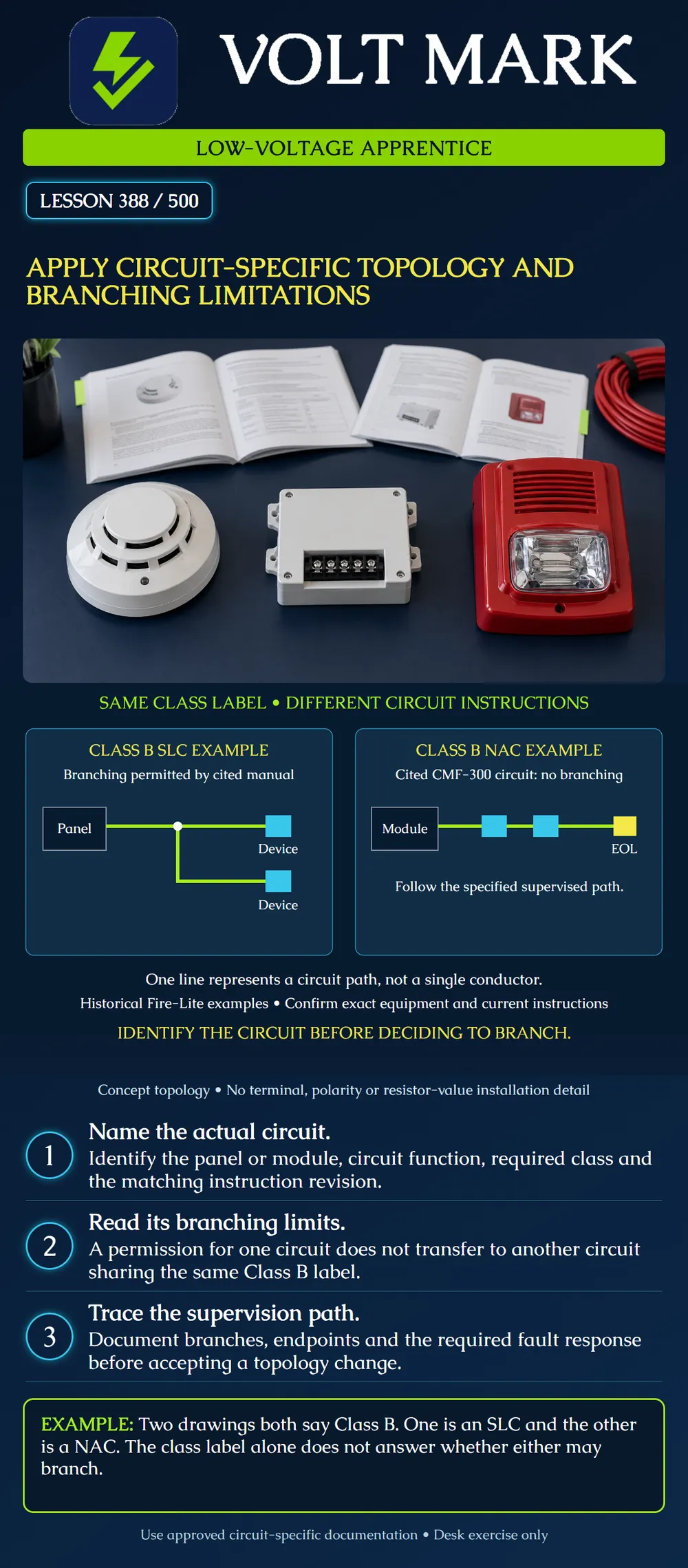
Identify the exact circuit before applying a branching rule. Compare a proposed topology with the applicable equipment documentation and preserve the intended supervision and fault response.
Each line represents a circuit path, not one conductor. The left panel illustrates a branched signaling line circuit, or SLC. The right panel illustrates a notification appliance circuit, or NAC, with its end-of-line location identified conceptually. Device blocks are abstract. Terminal numbers, polarity, external power connections and resistor values are intentionally absent; this is not a wiring installation drawing.
Fire-Lite's SLC Wiring Manual 51309, revision R3, July 29, 2019, permits T-tapping for its described two-wire Class B SLC arrangement. The same manual's CMF-300 Class B NAC instructions prohibit branching. It also requires the combined SLC branch lengths to remain within the applicable system manual's limits. These historical examples demonstrate why “Class B” alone cannot settle a branching question. Use the instructions for the actual equipment, configuration and revision.
A topology is the arrangement of connections: where a path begins, which devices it reaches, where it divides and where it terminates or returns. Trace it from a named circuit output. Do not start with an unlabeled line and guess which system behavior it represents.
Build a comparison record containing:
Leave an item unresolved when its evidence is missing. A familiar-looking arrangement is not evidence that the specific equipment supports it.
A technician receives two classroom sketches named “Class B.” Sketch One is attached to an SLC instruction page. Sketch Two is attached to a notification-module instruction page. A proposed revision adds a branch to both sketches because the drafter thinks the shared class label means the connections can be identical.
The apprentice's useful response is to separate the two records and identify the circuit-specific requirements. Copying a permission from Sketch One into Sketch Two does not resolve the second design. The poster makes this contrast visible without instructing a field alteration.
A better revision request names the affected output and the exact instruction figure, describes the proposed branch, lists affected endpoints and asks the responsible reviewer to reconcile the topology. “Add a tee here” does not contain enough information.
On paper, follow each endpoint back toward its source. Mark where a proposed change would split or rejoin the path. Ask what the approved documentation says should happen when the path is interrupted, and which devices would be affected. An intended trouble indication and continued operation are different questions; record both where required.
Do not infer that adding a return line automatically establishes an approved pathway class. Do not infer that normal operation proves every fault will be detected as required. A topology review needs the documented performance basis and the applicable verification process. This lesson does not prescribe a live open-circuit or short-circuit test.
An end-of-line device shown in a manufacturer's circuit is part of that circuit's specified arrangement. Do not relocate it, copy its value to another output or improvise extra terminations from this concept diagram. Resolve the complete circuit documentation.
For a classroom sketch, label three distinct cable segments A, B and C. Their measured route lengths are 120 ft, 80 ft and 65 ft. These are non-overlapping segments; any shared portion is already included once in A.
The total drawn cable route is: 120 + 80 + 65 = 265 ft. A proposed new, separate 35 ft segment changes that total to: 265 + 35 = 300 ft.
These sums are not an acceptance limit. They do not establish allowable resistance, capacitance, device count, voltage drop, address capacity or fault performance. To compare a real circuit against a manufacturer's limit, use the exact quantity and measurement convention specified by that manufacturer. Do not confuse total route length with source-to-end distance or twice the route length for a conductor-pair resistance calculation.
Keep the original and proposed drawings distinguishable. Record the branch locations and endpoint identifiers explicitly so that a reviewer can reconstruct the change. If the relevant figure prohibits the proposal, refer the conflict for a revised design. If branching is permitted, verify all remaining applicable limitations rather than marking the entire system accepted from that single permission.
Consulted October 1, 2026: Fire-Lite SLC Wiring Manual, 51309:R3, July 29, 2019, sections 2.2.1, 3.2 and 6.3.1; opened from Honeywell's official historical/discontinued-document location: https://buildings.honeywell.com/content/dam/hbtbt/en/documents/document-lists/firelite/discontinued-products/51309.pdf
The source is used for the narrow contrasting examples, not as a claim of current suitability for every panel. A Siemens document was located but direct opening failed and its specifications are not used. No secondary code mirror is relied upon. The record template, scenarios and arithmetic are original teaching material.
Verify the adopted requirements, current equipment instructions and approved project documentation.
Mistake: Copying an SLC T-tap permission to a notification circuit. Correction: Identify the actual output and use its circuit-specific branching and supervision instructions.
Mistake: Counting a shared cable segment once for each branch endpoint. Correction: Mark distinct segments and follow the manufacturer's length convention before totaling the route.
Mistake: Moving the end-of-line device to a convenient box. Correction: Keep the specified termination arrangement and refer a conflicting route for design resolution.
Texas journeyman, 15 questions, scored by topic against the 70% mark. No card, and no account needed to start.
Free study material for low-voltage apprentices. This is a national foundation course: requirements differ by state and by local jurisdiction, and a practice that is common in one place is not a rule everywhere. Nothing here is a licence, a certification, or authority to work unsupervised, and completing it does not count as apprenticeship hours or continuing-education credit. Check the codes adopted where you are working, the licensing authority for that work, and your employer's safety programme. VoltMark is not affiliated with, endorsed by, or sponsored by NFPA, OSHA, NICET, BICSI, FOA, or any state or local licensing authority.

Electrician licensing exam prep: practice questions, timed exam simulations, and step-by-step help finding every answer in the NEC.