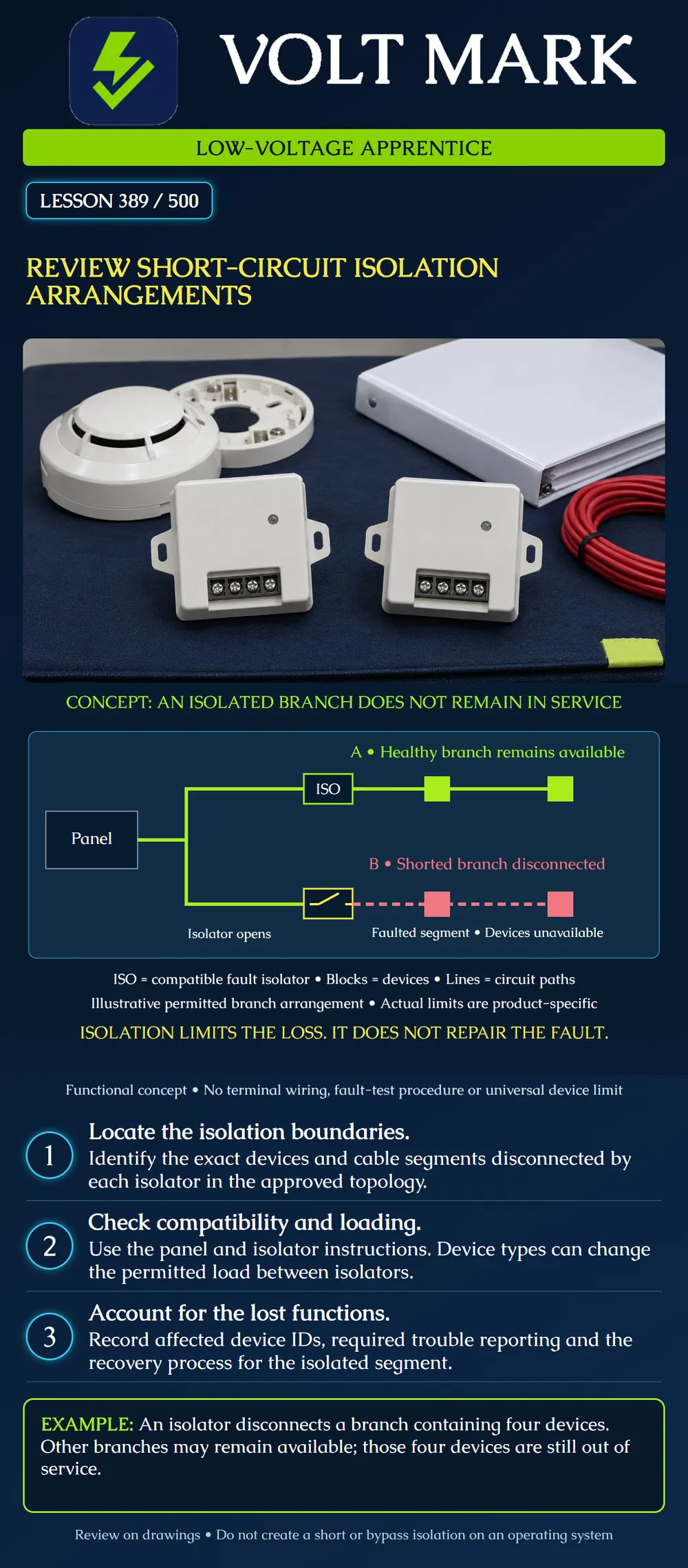
Locate the part of a signaling line circuit that an isolation arrangement disconnects during a short circuit. Identify the functions lost in that part and the documented basis for continued operation elsewhere.
The Fire-Lite I300 instruction sheet I56-3626-002 describes an isolator that allows part of a communications loop to keep operating during a short. It requires a listed compatible panel and warns that the permitted number of devices between isolators varies with device types. Its illustrated arrangement uses isolators to disconnect the affected group.
The historical Fire-Lite SLC Wiring Manual 51309:R3, section 4, also illustrates isolated branches and groups. It describes trouble reporting for addressable devices disconnected in an isolated segment. Its Class A example feeds unaffected portions from the appropriate outgoing and return sides. These are different arrangements; a drawing of one must not be treated as the wiring instructions for the other.
The I300 instructions describe automatic restoration after the short is removed. Automatic reconnection is not, by itself, proof that the cause was corrected, every affected function works or project restoration requirements are complete.
Start at the named panel output and identify every path feeding the proposed segment. Mark the isolator model and its boundaries, including branches, returns and any devices located between boundaries. Write the affected device identifiers inside the segment on a review copy.
A boundary drawn in the wrong location can produce an incorrect impact list. A device physically close to a fault is not necessarily on the same electrical segment. Use circuit connectivity, not floor-plan distance, to determine the proposed group.
Keep the device schedule beside the topology. A monitor module can represent a function beyond the module itself. A segment containing only a few addresses might still affect several important building functions. Count addresses when needed, but also describe what those addresses do.
A short between conductors, an open path and a connection to ground are different fault conditions. An isolator intended to respond to a short is not a repair for a broken conductor, and it is not evidence of protection against every other failure. Match the condition to the documented equipment behavior.
Ask two separate questions: what part is unavailable, and what indication should identify that condition? Do not equate a trouble indication with a fire alarm. Do not assume that because another branch operates, the isolated branch is acceptable to leave unavailable.
A fictional review drawing has three branches: A: seven device addresses. B: four device addresses. C: six device addresses. For this exercise only, assume the approved arrangement isolates a short entirely within B while A and C remain available.
Total before the fault: 7 + 4 + 6 = 17 addresses. Disconnected in B: 4 addresses. Remaining on A and C: 7 + 6 = 13 addresses. Check: 13 + 4 = 17.
These numbers describe the invented drawing, not a manufacturer's device allowance. A count of four is not a recommendation for isolator spacing. The actual allowable arrangement must consider the specific devices, isolator loading, panel limits and project requirements.
Now assume B's four addresses are two detectors, a monitor module and a control module. Write all four IDs and their documented functions. The result is more useful than simply writing “four devices down.” Do not infer the controlled equipment's safe state without its interface documentation.
Prepare one row per proposed isolation segment with:
If the instructions and drawing disagree, record the conflict. Adding more isolators without a design review is not an adequate answer; isolator quantity, placement and equipment compatibility all need a documented basis.
Use the classroom drawing to mark a hypothetical short location and trace the stated response. Do not introduce a real short, remove wires or bypass an isolator to perform this lesson. Actual verification belongs to the approved site process with the responsible personnel and required precautions.
Consulted October 1, 2026; both opened: Fire-Lite I300 installation instructions I56-3626-002, copyright 2012: https://prod-edam.honeywell.com/content/dam/honeywell-edam/hbt/en-us/documents/manuals-and-guides/installation-guides/I56-3626.pdf?download=false Fire-Lite SLC Wiring Manual 51309:R3, July 29, 2019, section 4: https://buildings.honeywell.com/content/dam/hbtbt/en/documents/document-lists/firelite/discontinued-products/51309.pdf
Sources provide historical product examples, not a universal current arrangement. No model-specific numerical device limit is generalized. The diagram, review record and numerical scenario are original teaching aids. Verify current equipment instructions, approved design and adopted requirements.
Mistake: Assuming devices in an isolated segment remain operational. Correction: List the disconnected addresses and their functions separately from the portions that remain available.
Mistake: Locating the isolation boundary by physical proximity to the fault. Correction: Trace circuit connectivity, isolators and alternate feed paths on the approved topology.
Mistake: Treating automatic reconnection as a completed repair. Correction: Retain the fault cause and required verification/restoration evidence before closing the issue.
Texas journeyman, 15 questions, scored by topic against the 70% mark. No card, and no account needed to start.
Free study material for low-voltage apprentices. This is a national foundation course: requirements differ by state and by local jurisdiction, and a practice that is common in one place is not a rule everywhere. Nothing here is a licence, a certification, or authority to work unsupervised, and completing it does not count as apprenticeship hours or continuing-education credit. Check the codes adopted where you are working, the licensing authority for that work, and your employer's safety programme. VoltMark is not affiliated with, endorsed by, or sponsored by NFPA, OSHA, NICET, BICSI, FOA, or any state or local licensing authority.

Electrician licensing exam prep: practice questions, timed exam simulations, and step-by-step help finding every answer in the NEC.