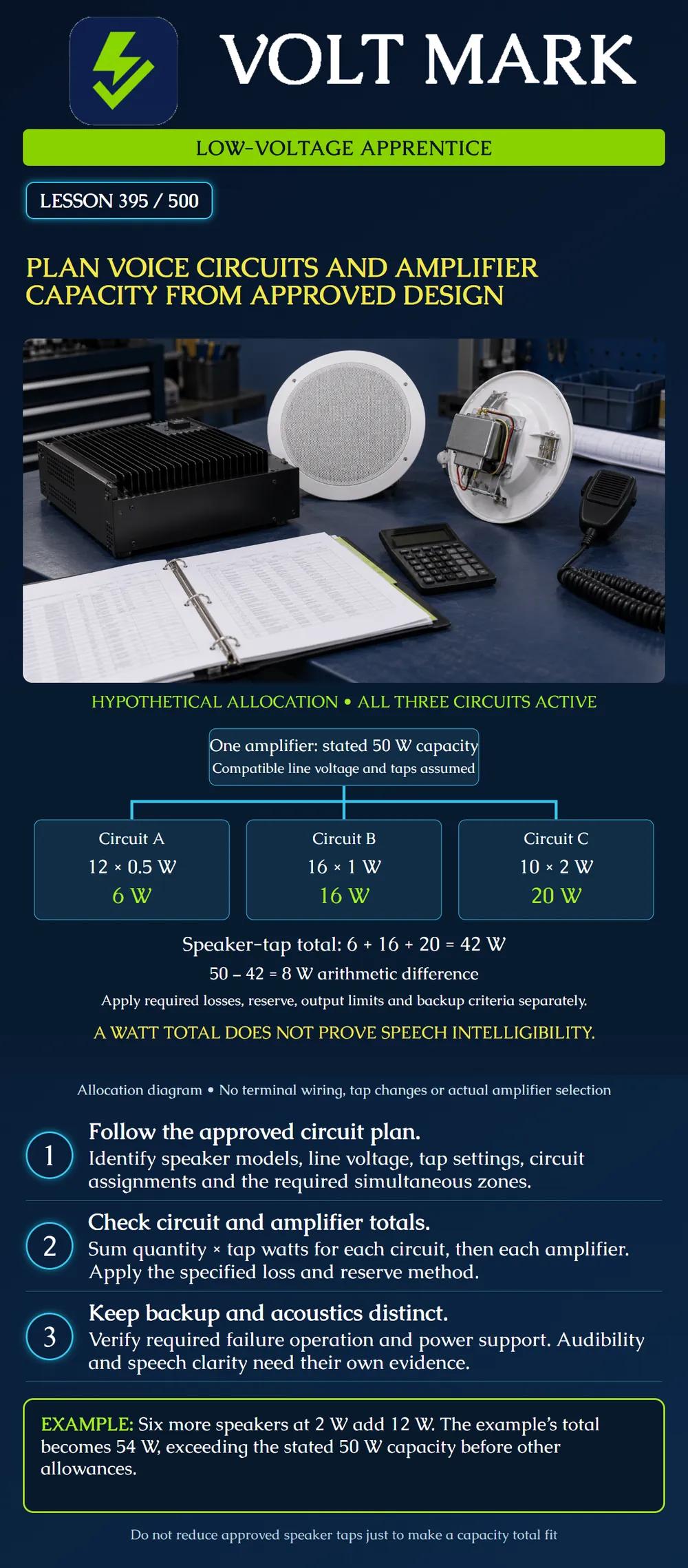
Read a speaker circuit schedule, total its assigned tap loads and reconcile those totals with amplifier allocation and required operating scenarios. Keep capacity arithmetic, backup operation and acoustic performance distinct.
The Fire-Lite ECC manual includes speaker-load entries by tap wattage and a model-specific maximum per amplifier. Honeywell's amplifier product information distinguishes adding an amplifier for additional capacity from configuring it as backup. These examples show why counting amplifier modules does not by itself establish usable normal or failure-mode capacity.
System Sensor's Voice Evacuation Systems Applications Guide treats audibility and intelligibility as separate design and verification concerns. A successful wattage calculation does not establish that occupants can understand a message.
Identify the amplifier and output configuration, speaker models, selected line voltage, tap schedule, circuit assignment and required message routing. Determine which circuits must operate together, including the all-call or emergency states required by the approved design.
Do not replace the stated operating case with an assumption that only one zone will ever be active. Also do not treat every connected circuit as independently powered merely because it has a separate terminal pair or identifier. Trace the shared amplifier allocation.
The poster shows one hypothetical amplifier feeding three assigned circuits. It is a functional allocation diagram rather than a terminal wiring plan. It assumes compatible line voltage and speaker tap settings; those assumptions must be verified for actual equipment.
The classroom schedule assigns: Circuit A: 12 speakers at 0.5 W each. Circuit B: 16 speakers at 1 W each. Circuit C: 10 speakers at 2 W each.
All three circuits are active in the stated exercise. Calculate: A = 12 x 0.5 = 6 W. B = 16 x 1 = 16 W. C = 10 x 2 = 20 W. Combined assigned tap load = 6 + 16 + 20 = 42 W.
The assumed amplifier capacity is 50 W for this example. Arithmetic difference = 50 - 42 = 8 W.
The 8 W difference is not an automatic allowance for adding speakers. Apply any required line-loss calculation, equipment limits, project reserve and operating conditions before considering additions. This exercise does not prescribe a universal reserve percentage or select an actual amplifier.
Tap wattage is used to allocate speaker load at the intended line-voltage configuration. Check that the selected speaker connection and amplifier line voltage correspond. Do not copy a tap label from another voltage configuration without reading the product's table.
A speaker-strobe may have an audio connection and a separate visible-notification load. The audio tap worksheet does not replace the strobe's current, voltage-drop or synchronization checks. Keep the assignments linked by device identifier while maintaining the correct units and supply boundaries.
A proposal adds six speakers to circuit C at 2 W each: Added load = 6 x 2 = 12 W. Revised circuit C = 20 + 12 = 32 W. Revised amplifier tap total = 6 + 16 + 32 = 54 W. Excess over the stated capacity = 54 - 50 = 4 W.
This proposal exceeds the assumed amplifier capacity before any other allowance. Moving these speakers to another output on the same amplifier does not remove their demand from that amplifier.
Reducing existing taps solely to make the arithmetic fit could undermine the approved acoustic design. Refer the change for a coordinated review of capacity, circuit arrangement and required sound performance.
Suppose a classroom equipment list contains two 50 W modules. Their installed nameplate sum is 100 W, but that alone does not say how the system is configured. One may be assigned to replace the other upon failure rather than to carry an additional simultaneous normal load.
For each required failure scenario, record the circuits transferred, the receiving amplifier, their combined load and the documented switching arrangement. Do not assume a backup resource can take over multiple failed amplifiers simultaneously unless the design and equipment support that case.
A failure-capacity worksheet should name the specific scenario. “There is a spare amp” does not identify what it can serve, how it is connected or what remains operational.
Review the applicable per-output limits as well as each amplifier total. Retain the cable schedule and required electrical-loss calculation. Account for the system's power and battery requirements using the manufacturer's method; an audio wattage total is not automatically the DC input-power demand.
Review audibility and intelligibility using the approved acoustic criteria and verification process. Room geometry, speaker placement, noise and reverberation can affect the result. Do not infer a compliant listening area from the remaining amplifier wattage.
Record drawing revision, amplifier ID, circuit IDs, speaker model/tap counts, line voltage, simultaneous activation case, computed load, applicable limits, required allowances and backup assignment. Keep the acoustic verification references and unresolved items with the record.
Consulted October 1, 2026; opened: Fire-Lite ECC-50/100 manual, LS10001-000FL-E, system-current worksheet Table 6.2: https://prod-edam.honeywell.com/content/dam/honeywell-edam/hbt/en-us/documents/manuals-and-guides/user-manuals/LS10001-000FL-E.pdf?download=false Honeywell Fire-Lite Audio Amplifier Module product page: https://buildings.honeywell.com/us/en/products/by-category/fire-life-safety/bi-directional-amplifiers/power-amplifiers/fire-lite-audio-amplifier-module System Sensor Voice Evacuation Systems Applications Guide, revision 02, February 2021: https://prod-edam.honeywell.com/content/dam/honeywell-edam/hbt/en-us/documents/manuals-and-guides/reference-guides/hbt-fire-VoiceEvacuationSystems_AppGuide_AVAG497.pdf
The worked schedule is original and hypothetical. Manufacturer examples are not a nationwide mandate or equipment recommendation.
Mistake: Treating the 8 W arithmetic difference as approved expansion capacity. Correction: Apply required allowances and per-output limits before assigning additional tap load.
Mistake: Counting a backup amplifier as extra normal operating capacity. Correction: Document the normal and required failure cases and trace which loads each amplifier must serve.
Mistake: Reducing speaker taps solely to make the wattage total fit. Correction: Refer the capacity conflict for coordinated electrical and acoustic review before changing the approved tap schedule.
Texas journeyman, 15 questions, scored by topic against the 70% mark. No card, and no account needed to start.
Free study material for low-voltage apprentices. This is a national foundation course: requirements differ by state and by local jurisdiction, and a practice that is common in one place is not a rule everywhere. Nothing here is a licence, a certification, or authority to work unsupervised, and completing it does not count as apprenticeship hours or continuing-education credit. Check the codes adopted where you are working, the licensing authority for that work, and your employer's safety programme. VoltMark is not affiliated with, endorsed by, or sponsored by NFPA, OSHA, NICET, BICSI, FOA, or any state or local licensing authority.

Electrician licensing exam prep: practice questions, timed exam simulations, and step-by-step help finding every answer in the NEC.