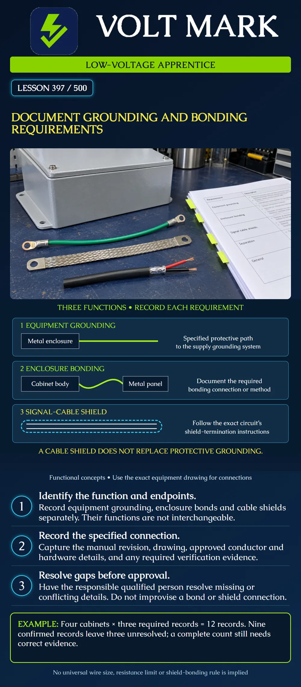
Create a traceable record of grounding, bonding and shield requirements for fire-alarm equipment. Distinguish their functions and identify missing evidence without inventing field connections. This lesson addresses documentation and coordination at the low-voltage technician's interface with electrical work.
The first row represents a metal enclosure's specified protective connection to the supply grounding system. It does not depict a ground rod, a complete fault-current loop or a conductor-sizing rule. Equipment grounding contributes to the protective arrangement; a line in a drawing is not proof that the installed path is effective.
The second row represents bonding between cabinet metalwork where the equipment design requires it. Bonding provides electrical continuity between conductive parts. A required connection may depend on the listed construction and specified hardware. Do not assume that an arbitrary hinge, mounting screw or painted surface fulfills a bonding requirement. The example is conceptual and does not say that every metal door needs the same jumper.
The third row shows two signal conductors within a surrounding shield. Shield termination is a circuit-specific requirement. A shield may serve an interference-control function, but it is not automatically the equipment grounding conductor, a circuit return or a substitute for a required enclosure bond.
OSHA's general-industry wiring standard, 29 CFR 1910.304(g)(5), requires a permanent, continuous and effective grounding path from circuits, equipment and enclosures. Paragraph (g)(6) addresses equipment and metalwork to be grounded with stated exceptions. These provisions support the importance of a documented protective arrangement. They are not a complete design specification and do not replace the applicable construction rules, electrical code or equipment instructions.
Product example: Fire-Lite's ECC manual, LS10001-000FL-E:H, January 8, 2018, section 2.3.1 and Figure 2.6, describe its equipment grounding connection. Section 2.11 separately describes external data/audio shield handling and warns against using a cable shield as the enclosure earth ground. It gives different shield details for different arrangements. This is why neither “always bond both ends” nor “always bond one end” is a sufficient universal instruction. Use the exact model, circuit, topology and manual revision.
Begin with an equipment identifier and physical location. Add the model, approved drawing reference, manual revision and section. Record the function of the connection, its specified endpoints and the responsible trade. Keep equipment grounding, enclosure bonding, shield termination and signal-reference requirements in distinct entries.
Capture conductor material and size only from the applicable approved design and equipment requirements. Capture specified lug, terminal, connector, hardware and torque information when relevant, with its source. If a detail is missing, mark it unresolved instead of filling the space with a typical value. Do not publish a single wire size or resistance threshold as suitable for all fire-alarm cabinets.
Include the evidence needed for closeout: drawing revision, authorized inspection record, applicable verification result, verifier and date. A photo can help identify a connection, but it does not demonstrate contact quality, hidden routing or a complete protective path. Do not label a photograph “tested” unless an actual authorized test record exists.
This desk exercise assigns three required records to each hypothetical cabinet: an equipment-grounding record, a required enclosure-bond record and a shield-arrangement record. These three entries are assigned exercise requirements, not a universal cabinet checklist.
Cabinet A: three records confirmed. Cabinet B: two records confirmed. Cabinet C: one record confirmed. Cabinet D: three records confirmed.
Required records: 4 × 3 = 12. Confirmed records: 3 + 2 + 1 + 3 = 9. Unresolved records: 12 − 9 = 3.
Identify what is unresolved rather than simply reporting “75 percent done.” For example, Cabinet B may lack its specified bonding-hardware reference. Cabinet C may lack both its protective-connection verification and its circuit-specific shield drawing. The record count is correct only for this assigned exercise. It does not establish safe operation or approval.
If a connection is not applicable to a real product, record the approved basis for that conclusion. Do not invent a jumper merely to satisfy a template. Conversely, an empty field is not evidence that a requirement is inapplicable.
Suppose an approved drawing identifies one shield arrangement while a newer equipment submittal identifies another. Record the document numbers, revisions, circuit and affected equipment. Ask the responsible designer or manufacturer through the project process to resolve the conflict. Preserve the resolution with the final record. Do not silently change the drawing or physically move the shield.
If a required bond appears absent, document the observation within the authorized scope and escalate it. Do not disconnect protective conductors to investigate noise, remove grounding to clear a fault indication, or add improvised bonds to make an indication disappear. Circuit troubleshooting and electrical verification need the approved procedures and appropriately qualified personnel.
A “normal” panel display is not a substitute for grounding/bonding evidence. Ground-fault monitoring and the integrity of protective connections are different questions. Keep their records separate.
Use a fictional cabinet schedule or approved training drawing. For each connection, state: what function does it serve, where is it specified, what are its endpoints, and what evidence confirms the final arrangement? Highlight unknowns. Do not open a cabinet or perform field tests for this lesson.
Q1. Can the shield be substituted for the enclosure's protective ground?
Q2. Is every shield connected the same way on every fire-alarm circuit?
Q3. Do twelve filled records prove the installation is correct?
Q4. What should replace an invented conductor size?
Q5. Does a normal panel display prove all enclosure bonds are effective?
OSHA, 29 CFR 1910.304, especially (g)(5) and (g)(6): https://www.osha.gov/laws-regs/regulations/standardnumber/1910/1910.304 Fire-Lite Emergency Command Center Manual, LS10001-000FL-E:H, January 8, 2018, sections 2.3.1 and 2.11: https://prod-edam.honeywell.com/content/dam/honeywell-edam/hbt/en-us/documents/manuals-and-guides/user-manuals/LS10001-000FL-E.pdf?download=false
The diagrams and cabinet-record exercise are original. This is a national fundamentals lesson, not a finding that all jurisdictions use identical provisions.
Mistake: Using the cable shield as the enclosure's protective connection. Correction: Keep shield handling and equipment grounding separate and follow the exact documented endpoints.
Mistake: Assuming a painted hinge provides a required cabinet bond. Correction: Verify the listed construction and specified bonding hardware rather than inferring continuity from appearance.
Mistake: Copying one-end shield bonding onto every circuit. Correction: Identify the circuit, topology and equipment instructions before documenting the shield arrangement.
Texas journeyman, 15 questions, scored by topic against the 70% mark. No card, and no account needed to start.
Free study material for low-voltage apprentices. This is a national foundation course: requirements differ by state and by local jurisdiction, and a practice that is common in one place is not a rule everywhere. Nothing here is a licence, a certification, or authority to work unsupervised, and completing it does not count as apprenticeship hours or continuing-education credit. Check the codes adopted where you are working, the licensing authority for that work, and your employer's safety programme. VoltMark is not affiliated with, endorsed by, or sponsored by NFPA, OSHA, NICET, BICSI, FOA, or any state or local licensing authority.

Electrician licensing exam prep: practice questions, timed exam simulations, and step-by-step help finding every answer in the NEC.